KE2040Instruction Manual Ver2.01,REV04.2003.6.25.pdf - 第50页
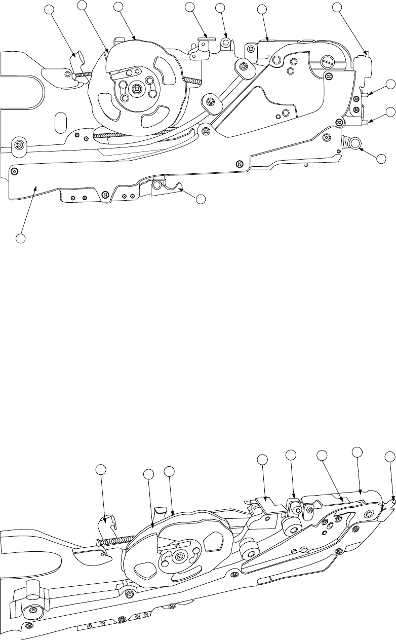
1 − 33 FF05/08 Parts ident ificat ion (2/2) 12 11 16 17 4 5 15 13 7 2 1 10 Figure 1.2.3.6 Detailed illu stratio n of the right sid e ① X axis ref erence pin A ⑧ Stopper ⑮ Guide cover ② X axis ref erence pin B ⑨ Free link…
1 − 32
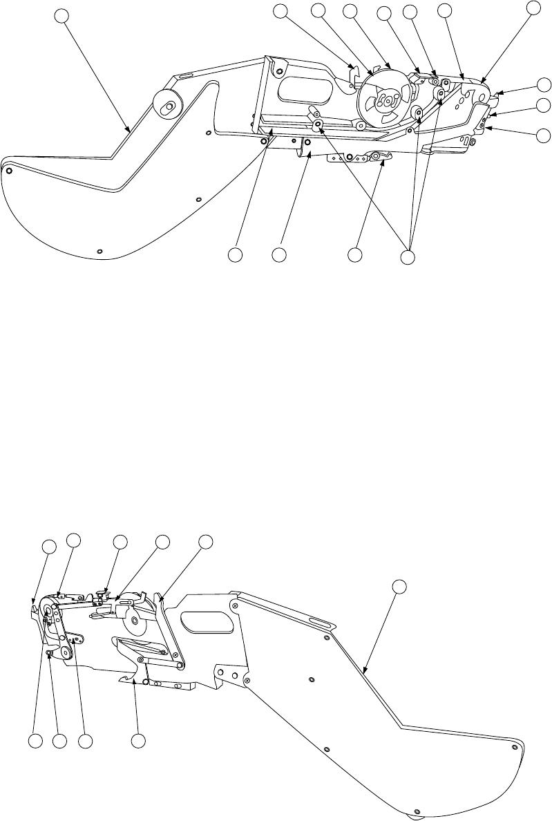
3. Tape feeder parts identification
The tape feeder uses a tape whose width is 8 mm, 12 mm, 16 mm, 24 mm, or 32
mm to supply components.
FF05/08 Parts identification (1/2)
12
11
10
16
4
17
6
5
1
2
14
19 15 13
18
Figure 1.2.3.4 Right side view
①
X axis reference pin A
⑧
Stopper
⑮
Guide cover
②
X axis reference pin B
⑨
Free link
⑯
Unreeling plate
③
Sprocket wheel
⑩
Tape holder
⑰
Unreeling guide roller
④
Upper cover
⑪
Cover tape fixing plate
⑱
Reel support
⑤
Upper cover hook
⑫
Lock release lever
⑲
Tape groove
⑥
Shutter
⑬
Lock holder
⑦
Knock lever
⑭
Tape guide
18
12
9
4
5
16
8
7
3 13
Figure 1.2.3.5 Left side view
1 − 33
FF05/08 Parts identification (2/2)
12
11
16
17
4
5
15
13
7
2
1
10
Figure 1.2.3.6 Detailed illustration of the right side
①
X axis reference pin A
⑧
Stopper
⑮
Guide cover
②
X axis reference pin B
⑨
Free link
⑯
Unreeling plate
③
Sprocket wheel
⑩
Tape holder
⑰
Unreeling guide roller
④
Upper cover
⑪
Cover tape fixing plate
⑱
Reel support
⑤
Upper cover hook
⑫
Lock release lever
⑲
Tape groove
⑥
Shutter
⑬
Lock holder
⑦
Knock lever
⑭
Tape guide
12
11
10
16
17
5
6
4
Figure 1.2.3.7 Detailed illustration of the top side
1 − 34
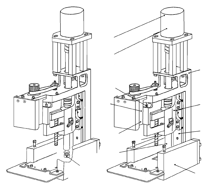
1.2.4 Head-related unit: parts identification
The head unit consists of the laser align sensor used to detect placement and angle
offsets of the component, and the Z slide shaft which can be moved up and down, or
be turned.
The Z slide shaft and the Z slide bracket of the Z axis are driven with rotations of the
ball screw.
The θ-axis encoder located on the upper section of the θ-axis motor detects the angle
of a component.
The machine is equipped with two units of FMLA head (L) and FMLA head (R) as
standard parts.
L Head-related unit (FMLA head) R Head-related unit (FMLA head)
Figure 1.2.4.1 Head-related unit
①
Nozzle outer
⑦
θ-axis encoder
②
Laser alignment sensor
⑧
Ball screw
③
Z-axis motor
⑨
Linear way
④
Z-axis encoder
⑩
Head-up spring
⑤
Z slide shaft
⑪
Head top bracket
⑥
θ-axis motor
⑫
Z slide bracket
⑦
⑥
⑪
⑫
⑨
②
①
⑤
⑧
④
③
⑩