KE2040Instruction Manual Ver2.01,REV04.2003.6.25.pdf - 第611页
7 − 129 − Shortcut keys On the “Ver ificat ion” single check dialog box, the f ollowing shortcut k eys are available. Table 7.7.1.3 Shortcut key s Key board Operation panel HOD key Action F10 ENTER Executes a single ve…
7 − 128
7.7.1.3.2 “Verification” single check dialog box
When you click the <VERIFY> button on the “Verification” component selection
dialog box shown in Figure 7.7.1.3.1, the following dialog box appears on the
screen.
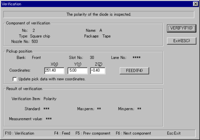
Figure 7.7.1.3.2 “Verification” single check dialog box
− Component of verification
Data on a component selected to be checked appears here.
− Pickup position
Data on the component pick-up position appears here. You can change the
pick-up position to that of the previous alternate component or the next
alternate component also.
① <FEED> button
When you click this button, the system knocks a feeder once to feed a
component (not available with a 32-mm paper tape).
② Check box “Update pick data with new coordinates.”
Check this check box if you want to store the result of teaching operation by
the HOD device onto Pick data.
◇ If you do not check this check box, the specified coordinates are applied
to the current pick-up position only.
− Result of verification
The “Verification item”, “Standard” value, the upper limit of allowable values
(“Max.perm.”) and the lower limit of allowable values (“Min.perm.”) appear
here.
− After checking a component, the system displays the measured value at
the item “Measurement value”.
7 − 129
− Shortcut keys
On the “Verification” single check dialog box, the following shortcut keys are
available.
Table 7.7.1.3 Shortcut keys
Keyboard Operation panel HOD key Action
F10 ENTER Executes a single verification check.
F4 Knocks a feeder.
F5 PREVIOUS Previous alternate component
F6 NEXT Next alternate component
ESC CANCEL Returns to the previous screen.
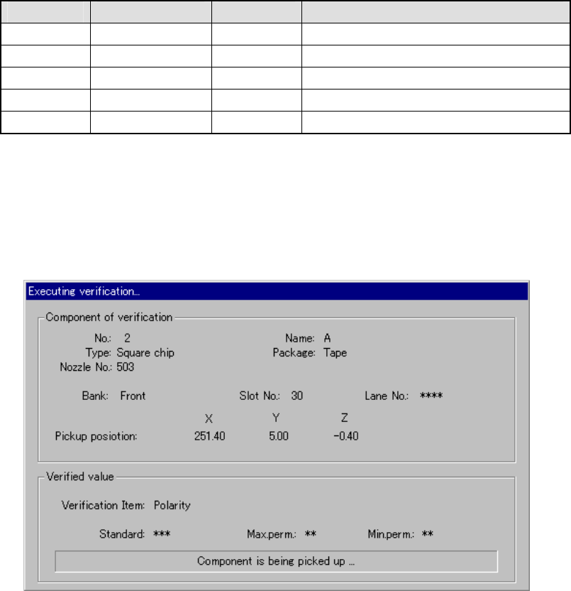
7.7.1.3.3 “Executing verification…” dialog box
When you click the <VERIFY> button on the “Verification” single check dialog box
shown in Figure 7.7.1.3.2, the following dialog box appears on the screen.
Figure 7.7.1.3.3 “Executing verification…” dialog box
− Component of verification
− Displays the data on a component that the system is checking.
− Verified value
− Displays the “Verification item”, “Standard” value, the upper limit of allowable
values (“Max.perm.”) , the lower limit of allowable values (“Min.perm.”) and the
current operation here.
7 − 130
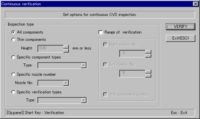
7.7.1.4 Continuous verification check
7.7.1.4.1 “Continuous verification” dialog box
When you click the [Tool] command from the menu bar, the [Check] command on
the “Tool” menu, and then [Continuous verification] command on the “Production”
menu, the following dialog box appears on the screen.
− Set the requirements for checking a component on this dialog box.
Figure 7.7.1.4.1 “Continuous verification” dialog box
− Inspection type
Specify whether to check only components
that satisfy a certain requirement among
components whose data is stored in
Component data.
① All components
The system checks all components whose
data is specified in Component data.
② Thin components
The system checks only components whose
height is specified in the Edit box or lower.
③ Specific component type
The system checks only components
selected in the combo box.
④ Specific nozzle number
The system checks only components that
use a nozzle specified in the combo box.
⑤ Specific verification types
The system checks only components whose
verification type is specified in the “Type”
combo box.