KE2040Instruction Manual Ver2.01,REV04.2003.6.25.pdf - 第632页
7 − 150 Enter the dist ance to be moved in units of step and the up and down range in each edit box. 部品側面 移動範囲 移動ステップ 現在レーザー高 さ 移動範囲 Figure 7.7.2. 5.4 Laser height judgment range (current height) ② Pick f ace of compo.…
7 − 149
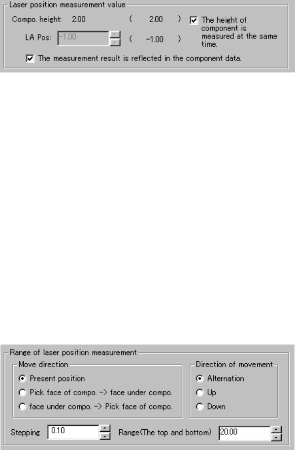
(1) Laser position measurement value
The descriptions required to measure laser height are displayed here.
Values set before measurement are displayed in parentheses.
① LA Pos (laser position)
You can change the laser height (position) as you like. The value
specified here is used as the current laser height when the system
starts judging if the laser height is within the appropriate range.
② "The height of component is measured at the same time."
When checked, the system measures the height of a component
before measuring the laser height. It automatically calculates the
laser height also at the same time. In this case, the laser height
automatically calculated is used as the current laser height when the
system judges if it is within the appropriate range. Therefore, you
cannot specify the laser height.
③ "The measurement result is reflected in the component data."
Check this check box if you want to store the measured laser height
into Component data immediately.
2) Range of laser position measurement
① Direction of movement
The system repetitively measures the laser height from the height
displayed in the "Laser position measurement value" column within
the range specified. When a component is centered with laser
successfully, the system finishes measuring the laser height.
Select one of the radio buttons below.
1) Alternation
2) Up
3) Down
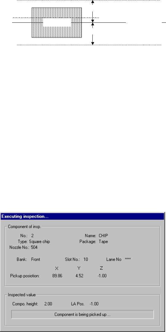
7 − 150
Enter the distance to be moved in units of step and the up and down
range in each edit box.
部品側面
移動範囲
移動ステップ
現在レーザー高さ
移動範囲
Figure 7.7.2.5.4 Laser height judgment range (current height)
② Pick face of compo. → face under compo.
③ face under compo. → Pick face of compo.
The system measures the component height within the range
specified here in addition to a value displayed in the "Range of laser
position measurement". The start point can be on either the
picked-up side or bottom side of a component.
3) Screen displayed while the system is inspecting the laser height in Single
check mode
The following dialog box appears on the screen while the system is
inspecting the laser height in Single check mode. Data on a component
being inspected, pick-up position and laser height are displayed on this
dialog box to show the current inspection progress.
Figure 7.7.2.5.4.3 “Executing inspection” dialog box
Side of a
component
Movement range
Movement range
Movement step
Current laser
height
7 − 151
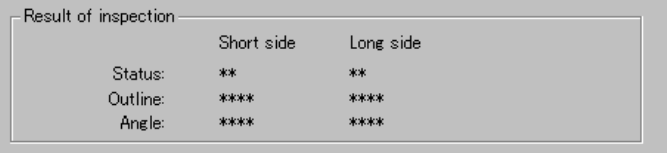
4) Result of inspection
The laser status value appears here if a component is centered with laser
successfully. The meaning of each item is the same as that for check
operation.