KE2040Instruction Manual Ver2.01,REV04.2003.6.25.pdf - 第780页
10 − 17 10.4.4 Light operation information W hen you select the [W indows] command on t he menu bar, t hen the [Lig ht Oper ation Inf ormation] comm and on t he displayed menu, t he screen appears as shown in Figure 10.4…
10 − 16
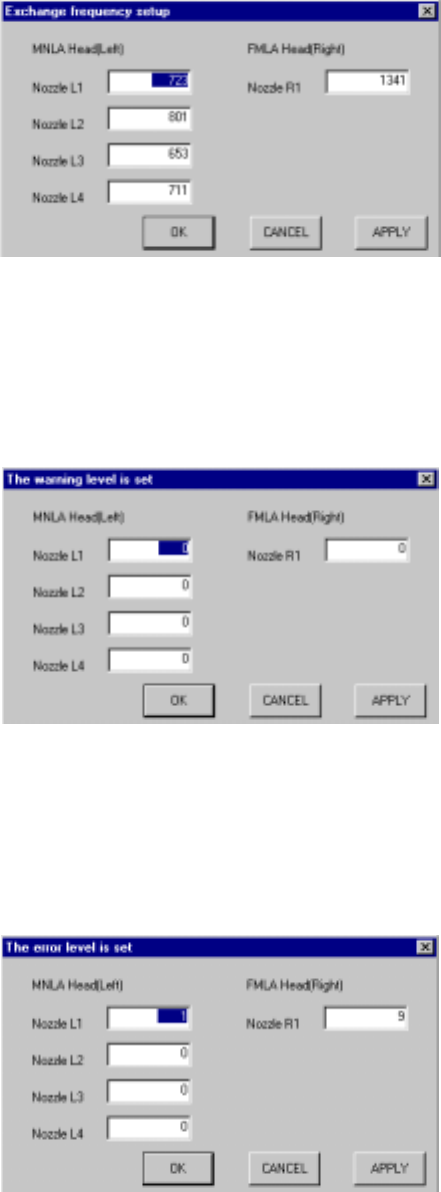
10.4.3.2 Setting the number of times for replacing a head
When you select the [Tool] command on the menu bar, the [Exchange frequency
setup] command on the displayed menu, then the [Each head] command the screen
appears as shown in Figure 10.4.3.2.1.
When you replace the head nozzle with another one, set this number to <0> to
initialize the number.
Figure 10.4.3.2.1 Exchange frequency setup dialog box
10.4.3.3 Setting the warning level
When you select the [Tool] command on the menu bar, the [The Warning level is set]
command on the displayed menu, then the [Each head] command, the screen
appears as shown in Figure 10.4.3.3.1.
Figure 10.4.3.3.1 "The warning level is set" dialog box
10.4.3.4 Setting the error level
When you select the [Tool] command on the menu bar, the [The error level is set]
command on the displayed menu, then the [Each head] command, the screen
appears as shown in Figure 10.4.3.4.1.
Figure 10.4.3.4.1 "The error level is set" dialog box
10 − 17
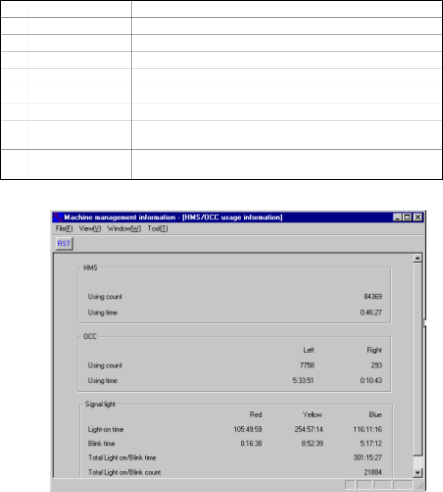
10.4.4 Light operation information
When you select the [Windows] command on the menu bar, then the [Light Operation
Information] command on the displayed menu, the screen appears as shown in Figure
10.4.4.1.
No. Item Description
1 HMS Using count Displays how many times the HMS was used.
2 HMS Using time Displays the time spent in using the HMS.
3 OCC Using count Displays how many times the OCC was used.
4 OCC Using time Displays the time spent in using the OCC.
5 Light-on time Displays the total time each signal light (red, yellow and blue) lit.
6 Blink time Displays the total time each signal light (red, yellow and blue) flashed.
7
Total Light on/Blink
time
Displays the total time the signal light lit or flashed.
8
Total Light on/Blink
count
Displays how many times the signal light lit or flashed.
Figure 10.4.4.1 Light Operation Information
10 − 18
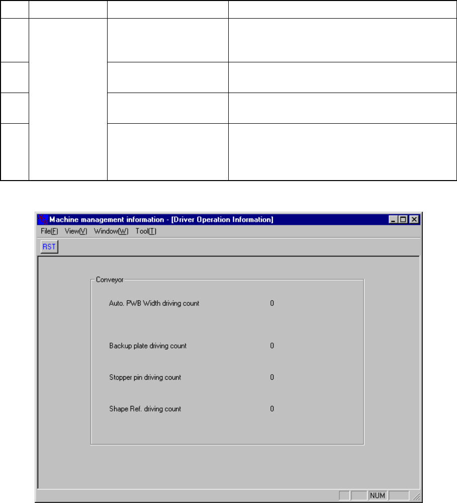
10.4.5 Driver operation information
When you select the [Window] command on the menu bar, then the [Driver Operation
Information] command on the displayed menu, the screen appears as shown in Figure
10.4.5.1.
No. Classification Item Description
1
Auto PWB Width driving
count
Displays how many times the automatic PWB
adjustment was performed since this information
was cleared the last time.
2
Backup plate driving
count
Displays how many times the backup plate was
driven.
3 Stopper pin driving count
Displays how many times the stopper pin was
driven.
4
Conveyor
Shape Ref. driving count
Displays how many times the machine has
produced PWBs by referring to the shape of
PWBs since this information was cleared the last
time.
Figure 10.4.5.1 Driver Operation Information