KE2040Instruction Manual Ver2.01,REV04.2003.6.25.pdf - 第790页
10 − 27 Step 2. W hen you click the <ATC Open>/ <ATC Close> but ton on the scr een shown in Figure 10. 5.1.2, t he f ollowing confirm ation dialog box appears on t he screen. Figure 10.5.1.2. 3 <A TC Open&…
10 − 26
10.5.1.2 Manual nozzle returning
If the laser head is stained, manually return nozzles.
To return nozzles manually, as described before, move a head manually where you
can remove a nozzle from it, and then remove the nozzle actually to return it onto the
ATC.
Step 1. Click the corresponding button for moving a head or opening/closing the
ATC.
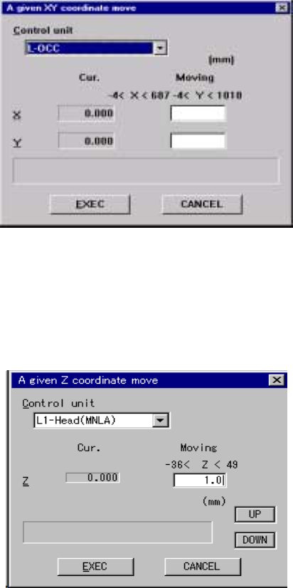
1. When you click the <XY Move> button on the screen shown in Figure 10.5.1.2,
the following screen appears. The origin of the XY-coordinates (0, 0) is the
left edge of the front side on which the operation panel is located.
Figure 10.5.1.2.1 “A given XY coordinate move” screen
2. When you click the <Z Move> button on the screen shown in Figure 10.5.1.2,
the following screen appears. The origin of the Z-axis (0, 0) is the PWB height,
and the top side is regarded as the positive direction while the bottom side is
as the negative direction.
Figure 10.5.1.2.2 “A given Z coordinate move” screen
10 − 27
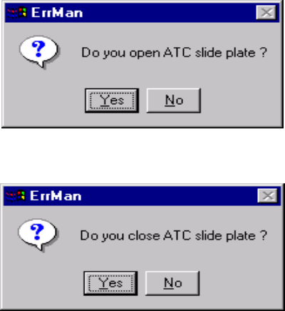
Step 2. When you click the <ATC Open>/<ATC Close> button on the screen shown
in Figure 10.5.1.2, the following confirmation dialog box appears on the
screen.
Figure 10.5.1.2.3 <ATC Open> confirmation screen
Figure 10.5.1.2.4 <ATC Close> confirmation screen
10.5.1.3 Checking to see if the laser alignment sensor window is stained
When the laser sensor window is stained, be sure to clean it.
Step 1. Clean the laser alignment sensor window.
See Section 14.3.3”Laser Alignment Sensor” of Chapter 14
“MAINTENANCE” for how to clean the laser alignment sensor window.
Step 2. Check to see if the laser alignment sensor window is not stained after
cleaning it.
Press the <Edge Disp> button on the “Nozzle On Head Information” dialog
box shown in Figure 10.5.1.
Clean the laser alignment sensor window until the displayed value gets
below the threshold displayed in red.
The Manual Control utility allows you to check the more detailed
information.
(See Section 9.2.3 “Laser Control” of Chapter 9.”)

10 − 28
(Referene)
A Trouble that occurs if you do not clean the stained laser alignment
sensor window
① Inappropriate placement precision (A recognition error occurs if stains are
located over the shadow of a component. Therefore, the machine may
not realize the regulated placement precision randomly.)
② Incensement of the number of discarded components (due to a
tombstone error, component dimension error and component orientation
error as well as laser error)
③ Lowered cycle time (because a laser recognition retry operation should
be performed)
④ Nozzle replacement error (because a nozzle is recognized with laser)
B Reason why the laser alignment sensor window is stained
The laser alignment sensor window may be stained due to dust, oil (oil of the
compressor and grease applied to the head are scattered), or dried-up
dust-like solder paste.
− Oil of the compressor:
See Section 14.2.1 “Air pressure” of Chapter 14 “MAINTENANCE”.
If oil or water is stored in the drain, remove it.
− Cleaning a nozzle:
See Section 14.3.4 “Nozzle” of Chapter 14 “MAINTENANCE” for how to
clean a nozzle.
<
<<
<Checkpoint>
>>
>
① Check to see if the Z-slide shaft section is greased too much.
② Check to see if any solder paste is stuck to a tip of a nozzle. If you judge
that a nozzle is not in contact with any solder paste on a board, solder
paste sprayed with air may piles at the tip of a nozzle little by little.
In such a case, check to see if:
• The pitch of a feeder is shifted, or
• The used nozzle is too large for a component.