KE2040Instruction Manual Ver2.01,REV04.2003.6.25.pdf - 第858页
13 − 18 13.11 Handling a Portable Type Tray Server (DTS) If you att ach or remove a DTS while the XY axis or head is operating, the DTS may come in contact w ith a part that is moving, and y ou may be injured or the mach…
13 − 17
4. Operation
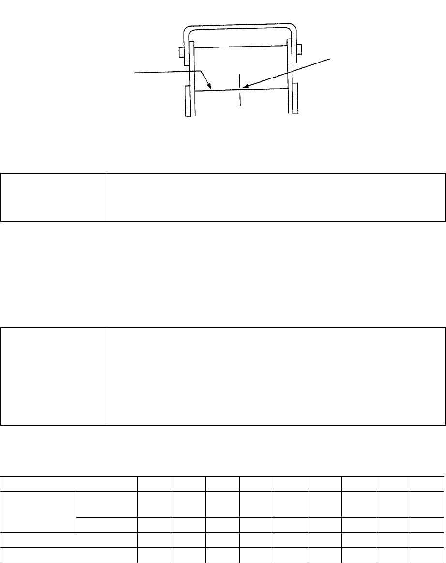
(1) Teaching
Fix the IC collection belt on the feeder bank, and teach the coordinates of the IC
collection belt position which is selected on the Machine setup menu.
Teaching position
Figure 13.10.3 Teaching operation
CAUTION
To avoid a risk of injury, do not place your hand in the machine, nor
move your face or head close to the machine during operation of the
HOD.
(2) Basic operation
The head of the main unit places an IC on the belt, and the component sensor
detects it. After 0.5 seconds, the IC is fed over the belt at the pitch you set. If
the belt gets full of ICs and stops, press the Reset switch to restart the machine
after removing ICs from the belt.
CAUTION
To avoid a risk of injury and prevent the machine from being damaged,
be sure to collect components only after detaching the IC collection belt
from the feeder bank or after you check to see if the machine stops
completely.
If you are to collect components from the IC collection belt being fixed
on the feeder bank, be sure to check to see if there is no person who
may start the machine unexpectedly.
Table 13.10.1 Number of ICs which can be collected
and the feeding pitch set with the rotary switch No.
Switch No. to be set 1 2 3 4 5 6 7 8 9
Equal or
less than
10 15 20 25 30 35 40 45 50 IC size (mm)
Over − 10 15 20 25 30 35 40 45
Belt feeding pitch (mm) 15 20 25 30 35 40 45 50 55
Maximum number of ICs 19 14 11 9 8 7 6 6 5
Optical axis
Teach the center of the
belt on the component
sensor optical axis.
13 − 18
13.11 Handling a Portable Type Tray Server (DTS)
If you attach or remove a DTS while the XY axis or head is operating,
the DTS may come in contact with a part that is moving, and you may
be injured or the machine may be damaged.
Do not attach or remove any DTS onto/from the machine while the XY
axis or head is operating.
After attaching the DTS onto the machine, secure the safety by
eliminating any clearance into which your hand or finger happens to be
put, for example by attaching an unused tape feeder on the clearance.
Procedure for attaching/removing a DTS
Refer to the Instruction Manual supplied with the DTS.
Attaching position (relation between the feeder bank number and the connector
bracket number)
The position of the DTS cable to be connected to the connector bracket may vary
depending on the feeder bank number the DTS is to use.
Table 13.11 DTS cable position
Feeder
bank
number
76~79 71~75 66~70 61~65 56~60 51~55 46~50 41~45 36~40 31~35 26~30 21~79 16~20 11~15 6~710 1~5
Rear 76 to 77 ① ② ③
Rear 71 to 75 ① ② ③
Rear 66 to 70 ① ② ③
Rear 61 to 65 ① ② ③
Rear 56 to 60 ① ② ③
Rear 51 to 55 ① ② ③
Rear 46 to 50 ① ② ③
Connector
bracket
number
Rear 45 ① ② ③
* ①: DTS P1-3-pin connector
②: DTS P2-3-pin connector
③: DTS P3-3-pin connector
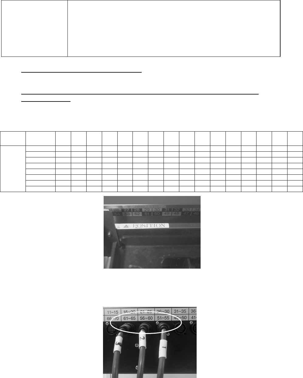
Figure 13.11.1 Example: When “△POSITION” is set to the number 53 (it is
assumed that this is set as the device enabled on the Setup menu).
The feeder bank numbers “51 to 55” are applied to this unit according to the table
above.
Figure 13.11.2 onnect the No. ① connector to the connector bracket number “51
to 55”, No. ②connector to “56 to 60” and No. ③ connector to “61 to 65.”
CAUTION
13 − 19
13.12 Handling a Gripper Nozzle
This nozzle is designed exclusively for the KE-2000 series of products to pick up
and/or place on a board a component whose top has no picked-up area, and it is
available to laser and vision recognition.
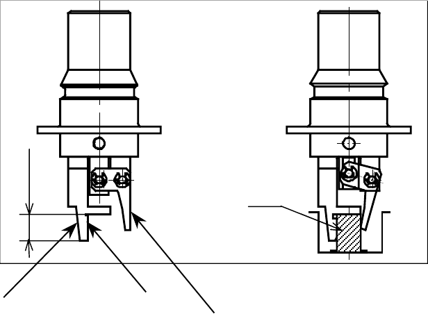
1. Features
The gripper nozzle uses its “fixed arm” and “swing arm” together exclusively to
pick up and/or place a component whose topside has no picked-up area. Its grip
strength is appropriate enough to pick up/place a component stably.
① Fixed arm
② Swing arm
Figure 13.12.1 Name of each part of a nozzle
①
①①
①
②
②②
②
Com
p
onent
Position against a
component is pushed
Len
g
th of a lu
g