KE2040Instruction Manual Ver2.01,REV04.2003.6.25.pdf - 第868页
13 − 28 13.13 Handling the Coplanarity Check Device 13.13.1 Overv iew of the coplanarity check device This device perf orms coplanarit y check f or electronic com ponents with its scanning type laser displacement g auge.…
13 − 27
3.4 Differences between a KE-2000 series of product and a KE-750/760
− The differences on operations are shown below when you use a gripper
nozzle:
Data type Setting item KE-750/760 KE-2000 series
Setup data Gripper nozzle
setting
Select the [g/Gripper nozzle]
command on the Setup menu, and
specify a number from 130 to 149
on the opened dialog box.
Select the [Read Nzl. data]
command on the “File” menu to
load information on a gripper
nozzle from a floppy disk. Then
operate the system in the same
manner as you do for a normal
nozzle.
Nozzle number 130 − 149 800 − 899
Centering method Laser only Both laser and vision
Component height Height of a portion that is
protruded from the tip of a nozzle
Height of a component itself
Laser height - 0.3mm − - 0.5mm Basically set laser height in the
same manner as you enter it
with a KE-750/760.
Enter the distance between the
edge of the fixed arm and the
molded part on which laser
beam impinges.
Component
data
Nozzle data in the
“Additional
information”
No setting item in Component
data.
(You have to perform teaching
operation if there is no Pick data
on a KE-2000 series of product.)
Specify the setting items, “Grip
Position”, “Horizontal
Clearance”, “Nozzle Direction at
Picking” and “Height
Adjustment”, which are designed
to require no entry for teaching a
component pick-up position.
Pick data Y coordinate Teaching is necessary for the
fixed side arm to be located far
from a component by about 1 mm.
Center of a component
Z coordinate The center of a gripper nozzle is
regarded as a reference position
of the top of a component.
Teaching is necessary for this side
to be the top of a component.
The tip of a nozzle is regarded
as the reference position.
(The tip of a gripper nozzle is
located at the height of the tip of
a standard nozzle.)
The system can pick up a
component relatively stably
without teaching its pick-up
position.
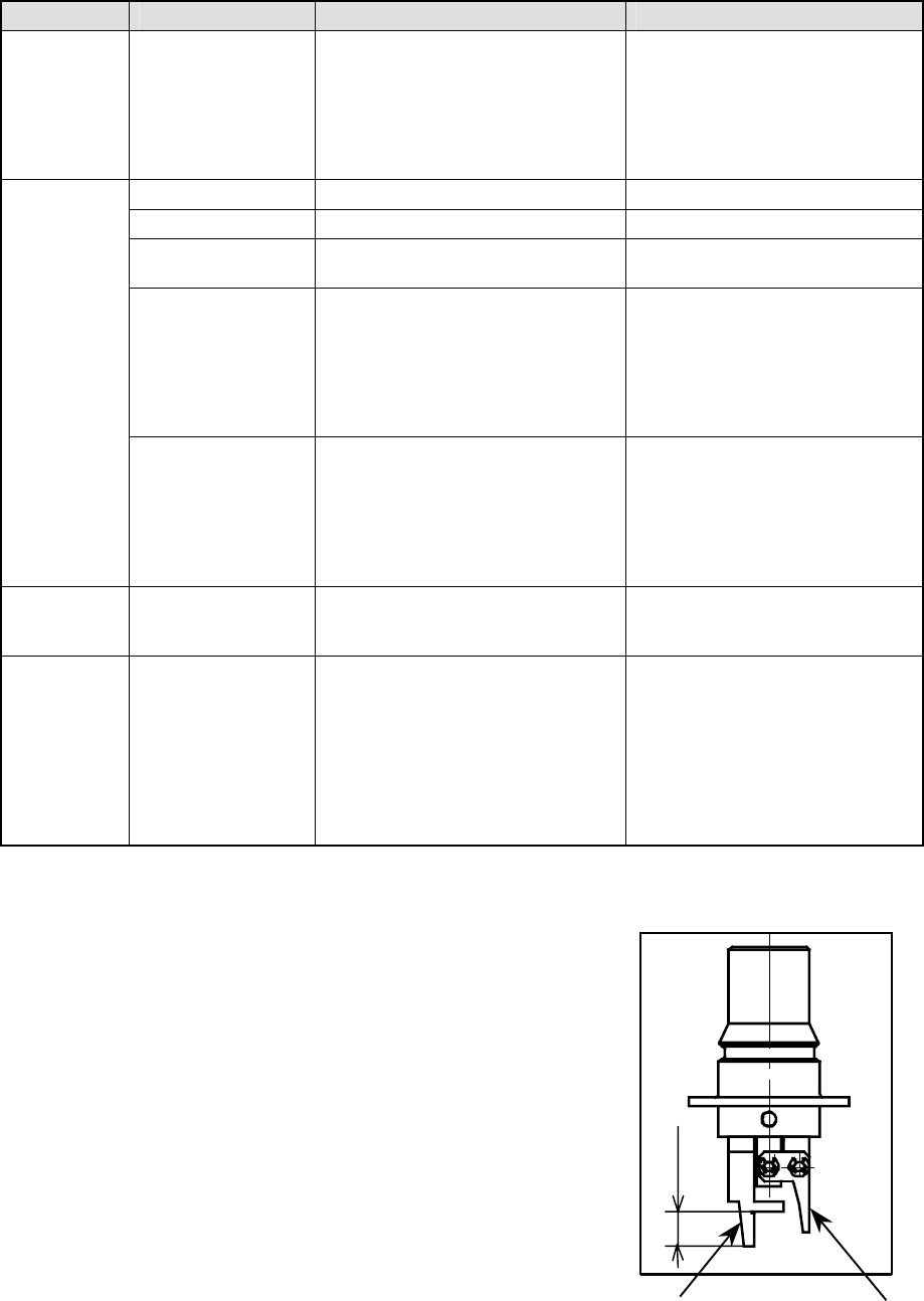
3.5 Direction a Gripper Nozzle Is Attached onto an ATC
View the ATC unit from its front, and
install a gripper nozzle onto the ATC
so that the fixed arm of the gripper
nozzle (1 in the figure below) can be
located on the rear, and the swing
arm (2 in the figure below) can be
located on the front.
①
①①
①
②
②②
②
Length of a lug
13 − 28
13.13 Handling the Coplanarity Check Device
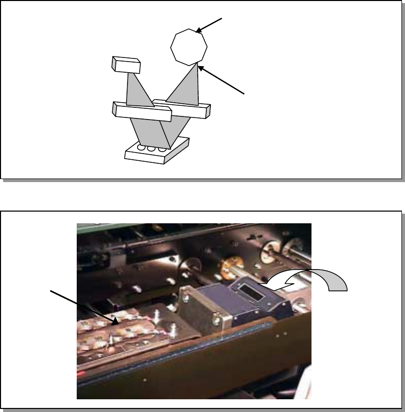
13.13.1 Overview of the coplanarity check device
This device performs coplanarity check for electronic components with its scanning
type laser displacement gauge.
A scanning type laser displacement gauge emits a laser beam to a certain spot of an
object, and use the light receptive lens to gather lights reflected or scattered from the
spot. Next, it generates an image of the spot over the position sensor to measure a
displacement without touching the object.
This device measures a 3-D shape of a component by moving the component at the
certain speed in the direction (Y direction) perpendicular to the laser scanning
direction (X direction) to obtain the metric image whose each picture element (pixel)
consists of height information.
− This device judges if a component is acceptable or not (with checking the height
of the electrode) based on the component information sent from a mounter in
advance and the obtained metric image.
Figure 13.13.1 Overview of the coplanarity check device
Figure 13.13.2 Appearance of the device
Polygon mirror
Laser mirror
ATC unit
Coplanarity
sensor
13 − 29
13.13.2 What to check with this device
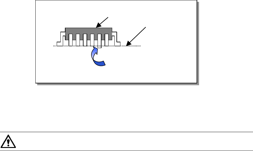
13.13.2.1 Colinearity check
The colinearity check inspects how much a side on which leads are located is bent in
the up/down directions.
− This check is performed with scanning a component with laser only once.
For example, for a component having four sides such as a QFP, the device scans
each of four sides with single scanning, and for a component having two sides
such as an SOP, the device scans each of two sides with single scanning.
Figure 13.13.2.1 Explanation of component check
“Colinearity” means parallelness. The machine can perform a colinearity
check for a lead component only.
13.13.2.2 Coplanarity check
Two methods are provided to obtain a coplanarity value:
Method regulated by EIAJ: appropriate for a QFP component.
Least squares method (by obtaining evenness of the terminal lowest side)
− At the factory, this device is set to obtain a coplanarity value with the method
regulated by EIAJ. (You can change this setting on the Machine setup menu.)
− This device checks a QFP component with EIAJED-7401-4, and an SOP
component with EIAJED-7304-1 or the least squared method.
− This device checks a ball component with EIAJED-7304.
− The method regulated by EIAJ regards a distance from the virtual plane to the
lowest point of the farthest terminal in the vertical direction of all terminals as a
coplanarity value.
Component to be checked
Line for measurement
Lead bent downward