KE2040Instruction Manual Ver2.01,REV04.2003.6.25.pdf - 第872页
13 − 32 13.13.3 Overv iew of the specificat ions (1) Applicable component s QFP, SOP,BG A, and Connector * O nly if they are r ecogniz ed by the VCS. For a ball component ( BGA), the system measures a ball component w ho…
13 − 31
13.13.2.3 Evaluation criteria
−
−−
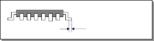
− Colinearity check (Applicable to a lead component only)
The device checks how much leads on each side are bent in the up/down
direction based on the value that is entered to the menu item “Tolerance”
displayed on the “COPLA CHECK DATA” dialog box invoked from the Vision data
screen.
− The position to be checked can be set with the menu item “Scanning Offset” on
the Vision data editing screen.
Figure 13.13.2.4 Explanation of the scanning position offset
−
−−
− Coplanarity check
The device checks how much a lead is bent in the up/down directions based on
the value that is entered to the menu item “Tolerance” displayed on the “COPLA
CHECK DATA” dialog box invoked from the Vision data screen.
Scanning position offset
13 − 32
13.13.3 Overview of the specifications
(1) Applicable components
QFP, SOP,BGA, and Connector
* Only if they are recognized by the VCS. For a ball component (BGA),
the system measures a ball component whose “contrast” is set to “All
ball-PWB” or “All balls-Ceramic” on the Vision data screen only.
A component whose data is created with a general-purpose vision is not
applicable.
(2) Resolution and precision
① Resolution: 1m
② Precision: 20 m (when measured with a JUKI standard gauge)
This device may not correctly judge a component whose terminal is
damaged due to contact with contact probe. It may not correctly judge a
lead component whose terminal is not rectangle-shaped or whose side
to be measured is not flat either.
(3) Measurement mode and dimensions of a component
Two measurement modes are provided: Standard mode and High-Precision
mode.
In Standard mode, the device scans a component at 80 mm/s with the sensor,
while in High-Precision mode, it scans a component at 20 mm/s.
Specifications of a component that can be measured in each mode are
shown below:
Table 13.13.1 Dimensions of a component in each mode
Item Standard mode High-Precision mode
Pitch 0.4 mm or more 0.3 mm or more
Lead width 0.18 mm or more 0.12 mm or more
Lead length 0.5 mm or more 0.5 mm or more
Batch
measurement
26 mm x 100 mm or less 26 mm x 50 mm or less
Lead
components
Component
size
Division
measurement
50 mm x 100 mm or less 50 mm x 50 mm or less
Pitch 0.81 mm or more 0.5 mm or more
Ball diameter 0.51 mm or more 0.3 mm or more
Batch
measurement
26 mm x 100 mm or less 26 mm x 50 mm or less
Ball
components
Component
size
Division
measurement
50 mm x 100 mm or less 50 mm x 50 mm or less
13 − 33
−
When you switch a measurement mode between Standard mode and
High-Precision mode, it takes three seconds to switch the rotating
speed of the polygon mirror. Therefore, if you are to produce both
components that should be measured in Standard mode and those
that should be in High-Precision mode, the production cycle time
becomes longer.
−
For a gull-wing lead, the length of a lead located on the foot section
should be 0.3 mm or more
−
Component height
* [If the dimensions of a component exceed those above, the
maximum component height should be 8 mm.]
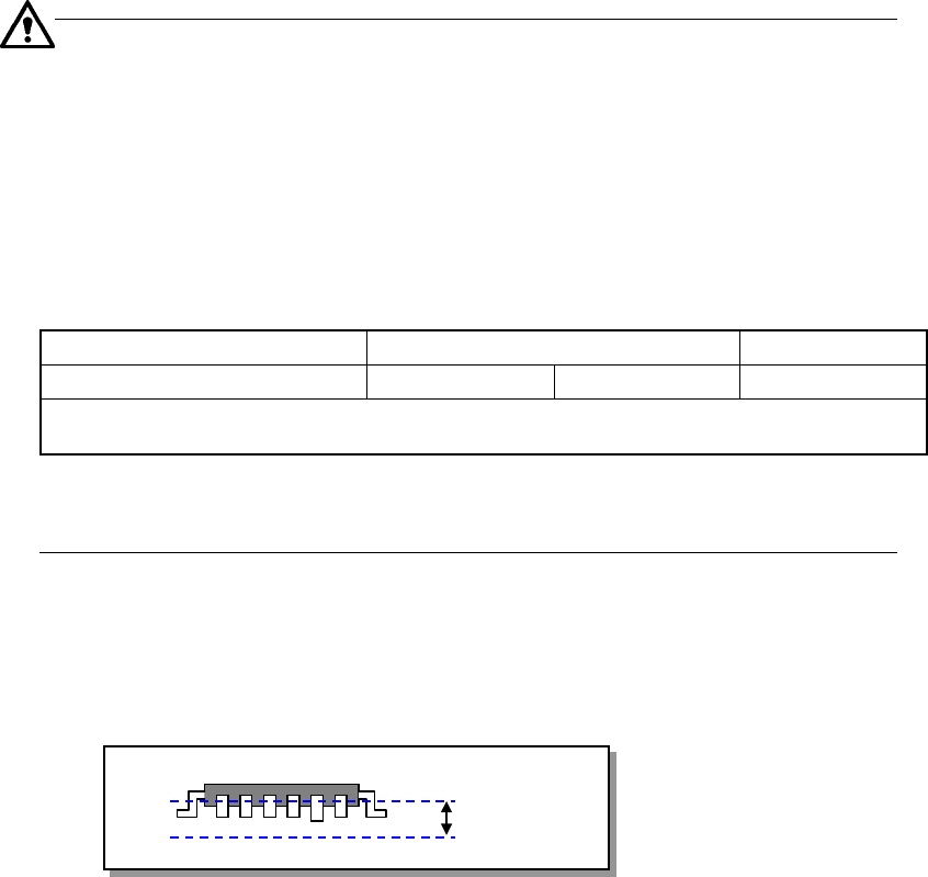
(4) Measurable Range
The measurable range of a lead is 1 mm or less. If the area indicated below
exceeds this range, an error occurs.
Figure 13.13.3.1 Measurable range
(5) Measurement retry operation
You can set how many times the machine should retry to measure a component
when a measurement error occurs (on the Machine setup menu).
(6) Parameters to be entered for measurement
① Tolerance: Coplanarity judgment value to be used for measurement
② Electrode size: width and length (applicable to a lead component only)
③ Lead Gloss: information on how glossy a lead is, Normal, Shiny and Dull.
(applicable to a lead component only)
④ Lead Brightness Threshold
⑤ Laser Strength: 0 to 7
⑥ Measurement Height Offset
⑦ Scanning Offset (Measurement position viewed form a tip of a lead)
(applicable to a lead component only)
⑧ AGC Adjustment: 0 to 5
⑨ Measurement Mode
Model name KE-2020 KE-2040
Component height (Maximum) 12mm 20mm 25mm
Note that the value described above is applied to a component when its longer side is 50 mm or
shorter, and the shorter side is 45 mm or shorter.
1mm