KE2040Instruction Manual Ver2.01,REV04.2003.6.25.pdf - 第874页
13 − 34 (7) O utput of measur ement result ① Judg ment: if the result is good or bad with compar ing to t he preset judgm ent value. ② I nfor mation on heig ht of all term inals and judgm ent (8) Laser st rengt h Laser: …
13 − 33
−
When you switch a measurement mode between Standard mode and
High-Precision mode, it takes three seconds to switch the rotating
speed of the polygon mirror. Therefore, if you are to produce both
components that should be measured in Standard mode and those
that should be in High-Precision mode, the production cycle time
becomes longer.
−
For a gull-wing lead, the length of a lead located on the foot section
should be 0.3 mm or more
−
Component height
* [If the dimensions of a component exceed those above, the
maximum component height should be 8 mm.]
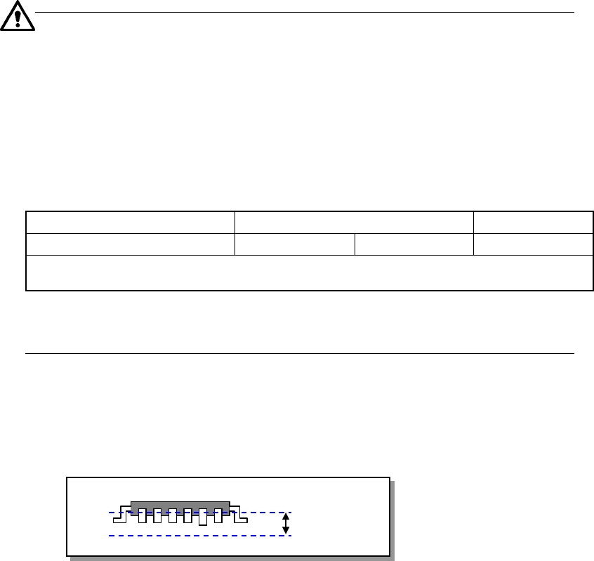
(4) Measurable Range
The measurable range of a lead is 1 mm or less. If the area indicated below
exceeds this range, an error occurs.
Figure 13.13.3.1 Measurable range
(5) Measurement retry operation
You can set how many times the machine should retry to measure a component
when a measurement error occurs (on the Machine setup menu).
(6) Parameters to be entered for measurement
① Tolerance: Coplanarity judgment value to be used for measurement
② Electrode size: width and length (applicable to a lead component only)
③ Lead Gloss: information on how glossy a lead is, Normal, Shiny and Dull.
(applicable to a lead component only)
④ Lead Brightness Threshold
⑤ Laser Strength: 0 to 7
⑥ Measurement Height Offset
⑦ Scanning Offset (Measurement position viewed form a tip of a lead)
(applicable to a lead component only)
⑧ AGC Adjustment: 0 to 5
⑨ Measurement Mode
Model name KE-2020 KE-2040
Component height (Maximum) 12mm 20mm 25mm
Note that the value described above is applied to a component when its longer side is 50 mm or
shorter, and the shorter side is 45 mm or shorter.
1mm
13 − 34
(7) Output of measurement result
① Judgment: if the result is good or bad with comparing to the preset
judgment value.
② Information on height of all terminals and judgment
(8) Laser strength
Laser: Class 1 (JISC6802, IEC60825-1)
850 mm infrared semiconductor laser (invisible light)
13 − 35
13.13.4 Operations
To perform coplanarity check, start up the Setup utility from the main screen, and
make settings on each screen invoked from the Setup utility.
Figure 13.13.4.1 Main screen
13.13.4.1 Machine setup
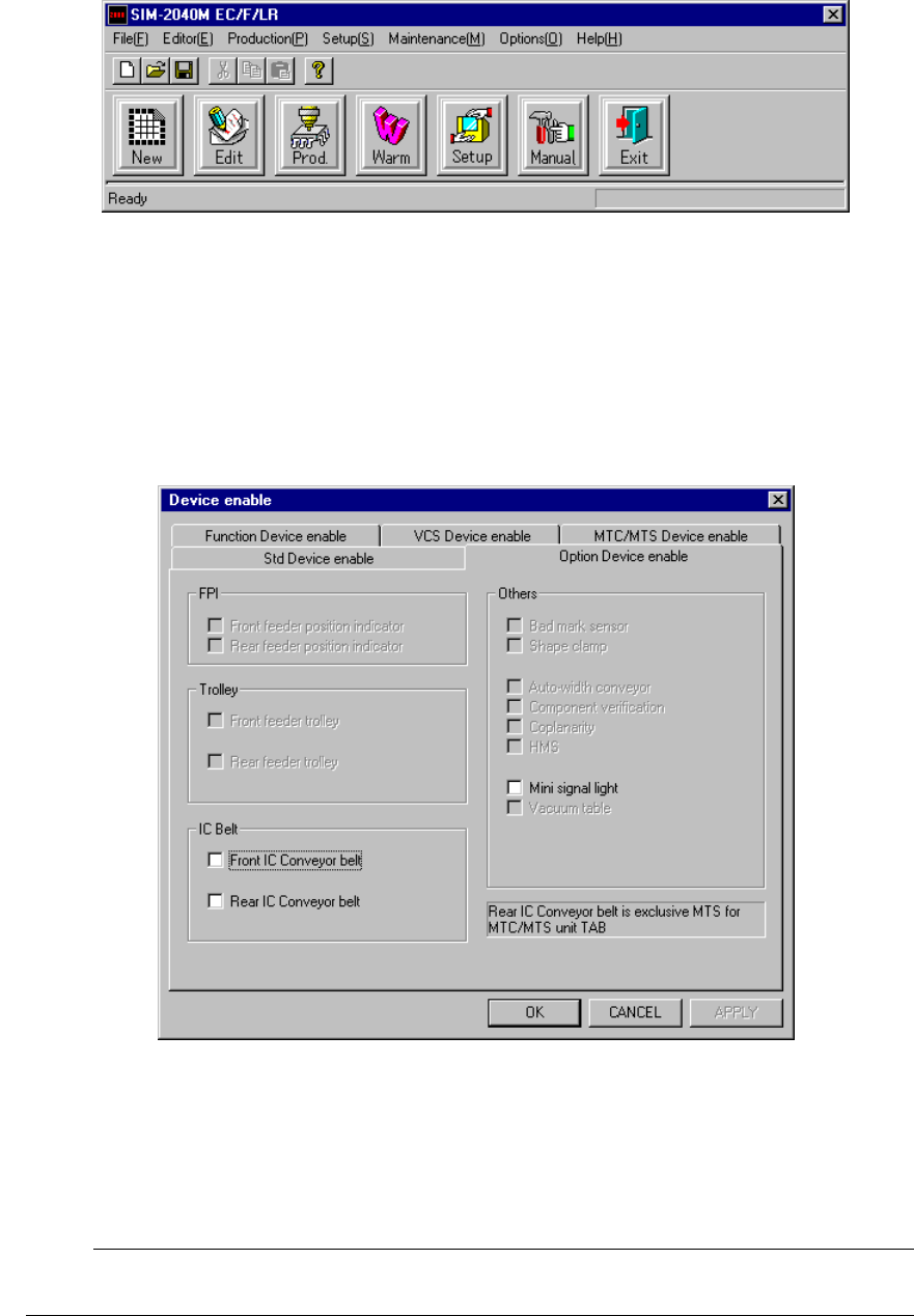
Select the [Setup] command from the menu bar, and the [Machine Setup], [Setup],
and [Device enable] commands in this order.
(For details, see Section 8.2.2.10.2 “Option Device enable” of Chapter 8 “MACHINE
SETUP”.)
Figure 13.13.4.2 Device enable dialog box
− Check to see if the check box “Coplanarity” provided as the “Others” menu item is
checked.
;
When you make all of the necessary settings, click the <OK> button. If you
do not have to make/change any setting, click the <CANCEL> button.
☞