KE2040Instruction Manual Ver2.01,REV04.2003.6.25.pdf - 第880页
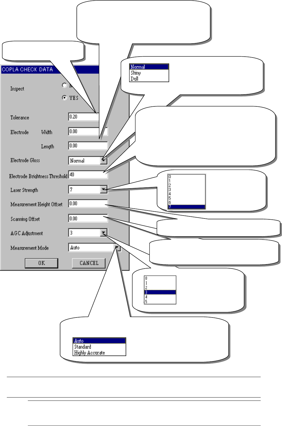
13 − 40 Figure 13.13.6 COPLA Check data screen When you make t he necessary settings, click the <OK> butt on. I f you do not have to make/change any set ting, click the <CANCEL> but ton. Note 1: If you use th…
13 − 39
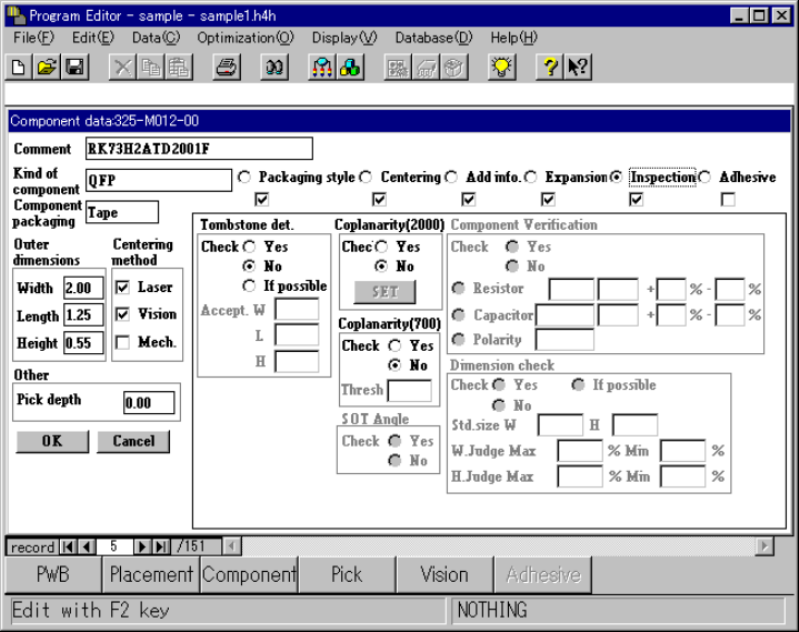
13.12.6 Editing data
To perform the coplanarity check, make the necessary settings on the screen shown
below.
− Select the [Component data] command, then [Coplanarity (2000)] Command on
the Program Editor screen.
(See 19 Copla of Section 5.2.3 “Detailed operations” of Chapter 5 “VCS”.)
− Check either the radio buttons “Yes” or “No” of the “Coplanarity (2000)” on
the dialog box below to select whether to perform a coplanarity check.
When you check the radio button “Yes”, the <Set> button is enabled.
(See Figure 13.13.6.1 Coplanarity selection screen.)
− Click the <Set> button. The “COPLA CHECK DATA” screen appears. (see
Figure 13.13.6.2 Coplanarity check screen.)
Figure 13.13.6.1 Coplanarity selection screen
13 − 40
Figure 13.13.6
COPLA Check data screen
When you make the necessary settings, click the <OK> button. If you do not
have to make/change any setting, click the <CANCEL> button.
Note 1: If you use the initial value of the machine, do not change the default
value “0.00”. If you set any other value here, the machine uses it.
The current initial value of the machine is 0.10 mm.
This value is used to
automatically control
gain when the device
receives a laser beam.
Normally, do not
change the default
Set the distance from the tip of a lead whose
coplanarity is to be measured. (unit: mm) Note 1
(You can set this value for a lead component only.)
Coplanarity judgment value:
(unit mm)
The electrode width and length are set to “0” by
default. By default, the lead width is 40 % of the
pitch specified as Vision data on the Vision data
screen, and the lead length is measured based on
50% of a value specified on the Vision data screen.
(
You can set this value for a lead com
p
onent onl
y
.
)
Select “Shiny” for a lead whose
surface is extremely shiny, while
select “Dull” for a lead whose surface
is extremely dull. (You can set this
value for a lead component only.)
The device emits a laser beam to a terminal to
calculate the height based on lights reflected from the
terminal.
“Lead Brightness Threshold” is a threshold for cutting
noise generated around the terminal so that the device
can obtain light reflected from the terminal.
Normally set “40”.
When a terminal is dark, set “0” or “30”. When it is
bright set
“
50
”
or
“
60
”
This indicates the
laser strength.
Normally set “7”
here.
Enter the offset for the height of a position to be
measured. Normall
y
set “0” here.
(
unit: mm
)
Set the measurement mode.
When you select “Auto”, the device
automatically sets its scanning mode
according to the table of (3)
Measurement mode and dimensions of a
component described under Section
13 − 41
13.13.7 Production
The system performs a coplanarity check during production, trial run or blank-run.
* The system does not perform a coplanarity check actually during blank-run.
13.13.7.1 Procedure for coplanarity check
① Picking of a target component
② Moving to the VCS position
③ Recognition of the target component vision by the VCS
④ Moving to the coplanarity sensor measurement start position
⑤ Checking if the device can perform a coplanarity check for the target component
⑥ Correction of the position based on the result of vision recognition
⑦ Performing coplanarity check for the component
⑧ Judging if the target component passes the check based on the result of
measurement by the coplanarity sensor
[Process after judgment]
8_1 Discarding the component
8_2 Placing the component
8_3 Pause
Figure 13.13.7 Process flow chart
Moving to the VCS position
①
②
③
④
⑤
⑥
⑦
⑧
Picking of the target component
Vision recognition by the VCS
Moving to the coplanarity sensor position
Correction of the component position
Coplanarity check
Judgment
End
Checking the
com
p
onent