KE2040Instruction Manual Ver2.01,REV04.2003.6.25.pdf - 第882页
13 − 42 − Flow chart of the coplanarit y check Note 1: The system checks coplanarity of a BGA or FBGA component in the least squares method only. Note 2: The system does not perform a colinearity check for a unidirection…
13 − 41
13.13.7 Production
The system performs a coplanarity check during production, trial run or blank-run.
* The system does not perform a coplanarity check actually during blank-run.
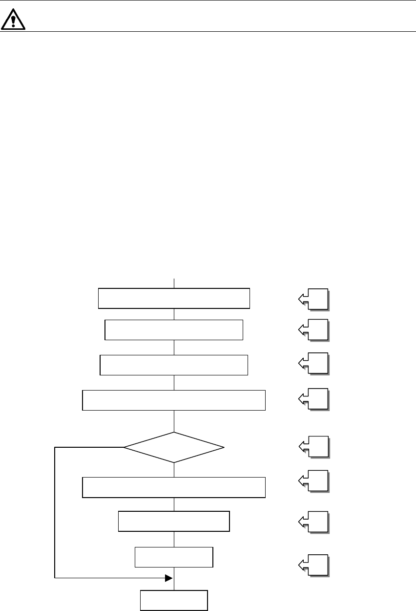
13.13.7.1 Procedure for coplanarity check
① Picking of a target component
② Moving to the VCS position
③ Recognition of the target component vision by the VCS
④ Moving to the coplanarity sensor measurement start position
⑤ Checking if the device can perform a coplanarity check for the target component
⑥ Correction of the position based on the result of vision recognition
⑦ Performing coplanarity check for the component
⑧ Judging if the target component passes the check based on the result of
measurement by the coplanarity sensor
[Process after judgment]
8_1 Discarding the component
8_2 Placing the component
8_3 Pause
Figure 13.13.7 Process flow chart
Moving to the VCS position
①
②
③
④
⑤
⑥
⑦
⑧
Picking of the target component
Vision recognition by the VCS
Moving to the coplanarity sensor position
Correction of the component position
Coplanarity check
Judgment
End
Checking the
com
p
onent
13 − 42
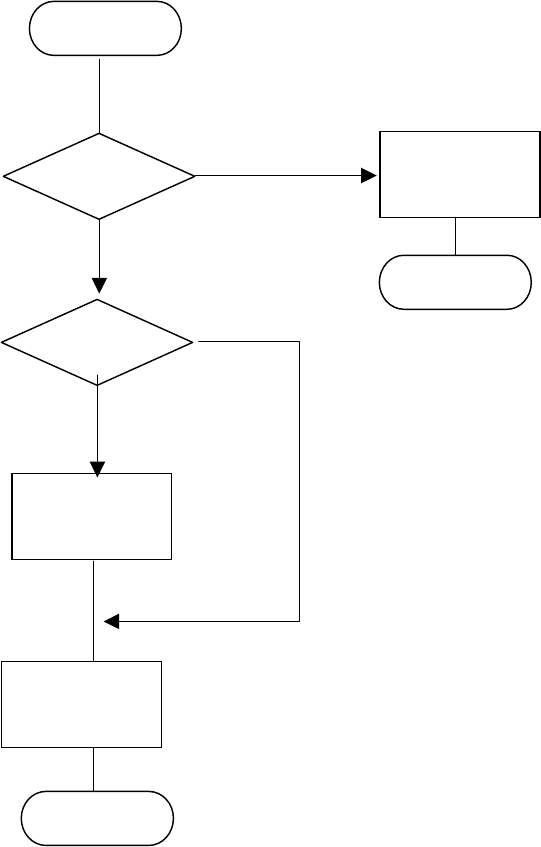
− Flow chart of the coplanarity check
Note 1: The system checks coplanarity of a BGA or FBGA component in the least squares
method only.
Note 2: The system does not perform a colinearity check for a unidirectional lead connector.
Note 3: The coplanarity check the system performs for a unidirectional lead connector is the
same as the colinearity check currently.
Figure 13.13.7 (1) Process flow (flow chart of the coplanarity check)
END
Colinearity
check
(see Note 2)
Coplanarity
check
(see Note 1)
Start
Unidirectional
lead connector ?
BGA
component ?
No
No
Coplanarity
check
(see Note 3)
Yes
Yes
END
13 − 43
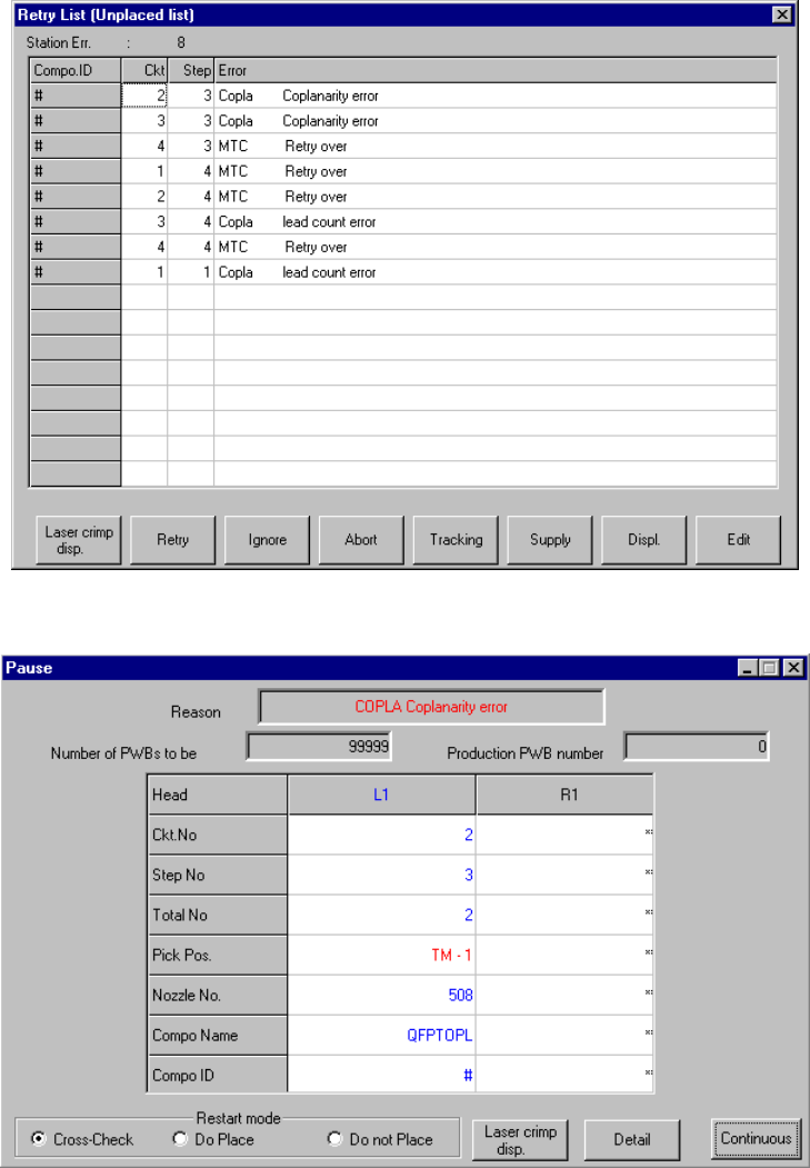
13.13.8 Error processing
When the device detects an error as the result of coplanarity check, the system
displays an error log when it does not place an error component on a board.
Figure 13.13.8.1 Error dialog box
Figure 13.13.8.2 Pause dialog box