KE2040Instruction Manual Ver2.01,REV04.2003.6.25.pdf - 第883页
13 − 43 13.13.8 Error processing W hen the device detects an err or as the result of coplanar ity check, t he system displays an error log when it does not place an er ror com ponent on a board. Figure 13.13.8. 1 Error d…
13 − 42
− Flow chart of the coplanarity check
Note 1: The system checks coplanarity of a BGA or FBGA component in the least squares
method only.
Note 2: The system does not perform a colinearity check for a unidirectional lead connector.
Note 3: The coplanarity check the system performs for a unidirectional lead connector is the
same as the colinearity check currently.
Figure 13.13.7 (1) Process flow (flow chart of the coplanarity check)
END
Colinearity
check
(see Note 2)
Coplanarity
check
(see Note 1)
Start
Unidirectional
lead connector ?
BGA
component ?
No
No
Coplanarity
check
(see Note 3)
Yes
Yes
END
13 − 43
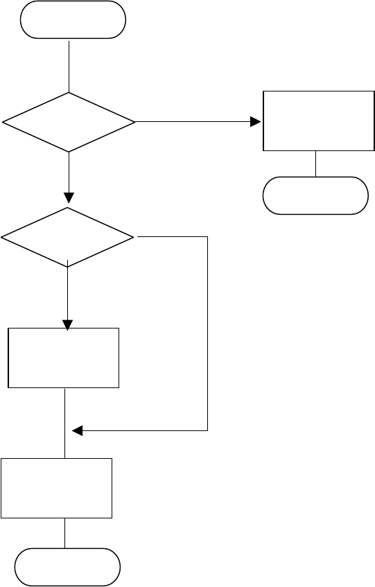
13.13.8 Error processing
When the device detects an error as the result of coplanarity check, the system
displays an error log when it does not place an error component on a board.
Figure 13.13.8.1 Error dialog box
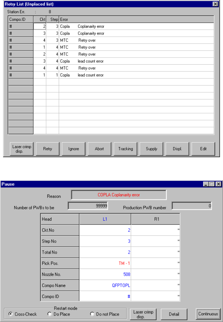
Figure 13.13.8.2 Pause dialog box
13 − 44
13.13.9 Overview of the coplanarity check operation
Movements of a component over the axis sensor during coplanarity check are
described below.
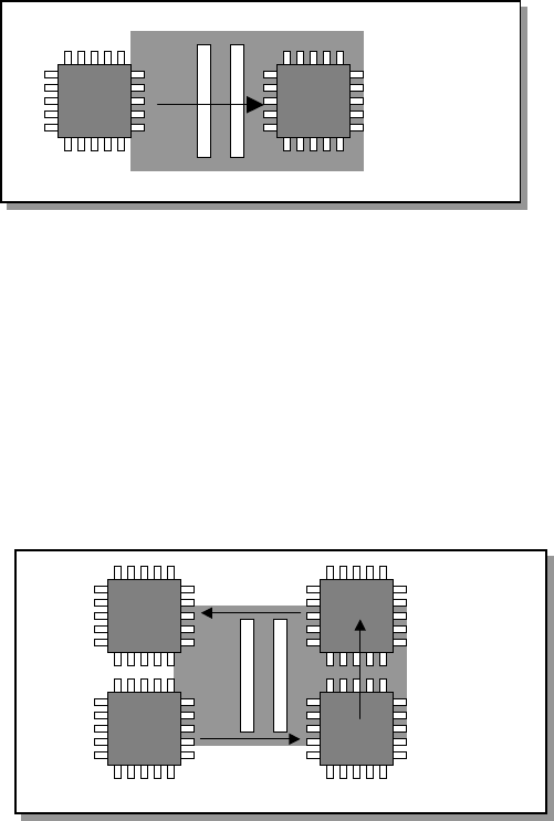
13.13.9.1 Batch component check
The device scans a component whose size is specified for “Batch measurement” in
(3) Measurement mode and dimensions of a component of Section 13.13.3 in a single
direction to measure it.
13.13.9.1 Batch measurement operation
13.13.9.2 Division component check
The device scans a components whose size is specified for “Division measurement”
in (3) Measurement mode and dimensions of a component of Section 13.13.3 as
shown in Figure below to measure it.
Figure 13.13.9.2 Division measurement operation