00191987-02.pdf - 第22页
User Manual External Power Supply Unit for the HS-50 / HS-60 / D4 Component Table 2.3 Overview 03/2006 Edition 22 Fig. 2.3 - 2 Back View (1) Compressed air conne ction (2) CAN bus connection (3) Mains connection combinat…
External Power Supply Unit for the HS-50 / HS-60 / D4 Component Table User Manual
03/2006 Edition 2.3 Overview
21
2.3 Overview
An external power supply unit is employed to power an HS-50 / HS-60 / D4 component table, in-
dependent of the placement machine.
The unit can be adjusted to the existing main voltage, 230 V or 115 V, from the outside, without
opening. As delivered, the unit is equipped for a main voltage of 230 V AC.
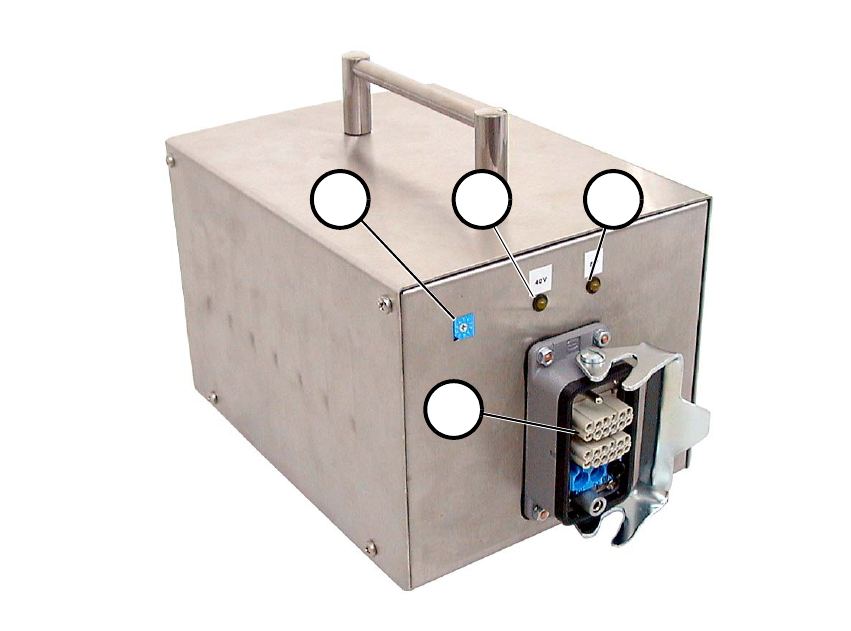
Fig. 2.3 - 1 Front View
(1) Table location switch
(2) Pilot lamp 40 V
(3) Pilot lamp 8 V
(4) Multifunction plug for component table
2
4
21 3
User Manual External Power Supply Unit for the HS-50 / HS-60 / D4 Component Table
2.3 Overview 03/2006 Edition
22
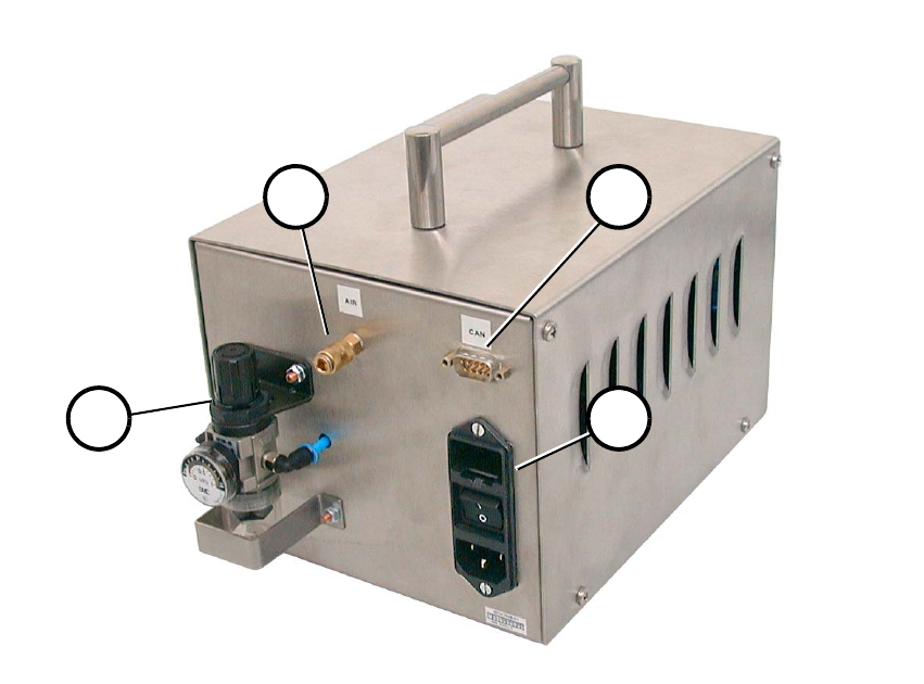
Fig. 2.3 - 2 Back View
(1) Compressed air connection
(2) CAN bus connection
(3) Mains connection combination
(4) Pneumatic system unit
1 2
34
External Power Supply Unit for the HS-50 / HS-60 / D4 Component Table User Manual
03/2006 Edition 2.4 Setup / Settings
23
2.4 Setup / Settings
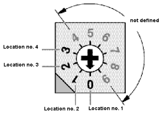
2.4.1 Setting the Location Number
If several (max. 4) power supply units are connected by means of a CAN bus, the location number
must be set (Fig. 2.4 - 1). 2
Zero corresponds to component table location No. 1; three corresponds to No. 4.The higher num-
bers are not defined. 2
2
2
2
2
2
2
2
2
2
2
2
2
Fig. 2.4 - 1 Location Number Switch (Front View)
Zero, i.e., location number 1, was set at the factory. 2