00191987-02.pdf - 第23页
External Power Supply Unit for the HS-50 / HS-60 / D 4 Component Table User Manual 03/2006 Edition 2.4 Setup / Settings 23 2.4 Setup / Settings 2.4.1 Setting the Location Number If several (max. 4) power supply unit s ar…
User Manual External Power Supply Unit for the HS-50 / HS-60 / D4 Component Table
2.3 Overview 03/2006 Edition
22
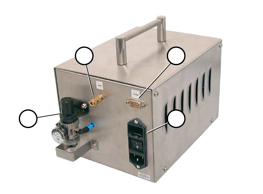
Fig. 2.3 - 2 Back View
(1) Compressed air connection
(2) CAN bus connection
(3) Mains connection combination
(4) Pneumatic system unit
1 2
34
External Power Supply Unit for the HS-50 / HS-60 / D4 Component Table User Manual
03/2006 Edition 2.4 Setup / Settings
23
2.4 Setup / Settings
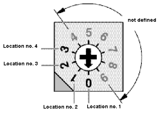
2.4.1 Setting the Location Number
If several (max. 4) power supply units are connected by means of a CAN bus, the location number
must be set (Fig. 2.4 - 1). 2
Zero corresponds to component table location No. 1; three corresponds to No. 4.The higher num-
bers are not defined. 2
2
2
2
2
2
2
2
2
2
2
2
2
Fig. 2.4 - 1 Location Number Switch (Front View)
Zero, i.e., location number 1, was set at the factory. 2
User Manual External Power Supply Unit for the HS-50 / HS-60 / D4 Component Table
2.5 Checking the Main Voltage and Perhaps Converting for It 03/2006 Edition
24
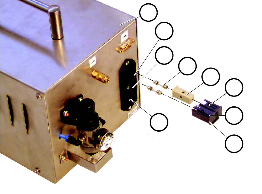
2.5 Checking the Main Voltage and Perhaps Convert-
ing for It
Fig. 2.5 - 1 Main Switch with Fuses and Input Voltage Adjuster
2
1. Turn the main switch (3 in Fig. 2.5 - 1) for the unit to OFF and make certain that the mains con-
nector is not plugged into the unit.
2. Unlock the snap lock (9) by pushing it up and pull out the black plastic insert (7) with the fuses.
3. Remove the two fuses (5).
4. Check to make certain that the two fuses are the correct ones:
2 ea. 1.25 A medium time-lag fuses are designed for 210-240 V AC.
2 ea. 2.5 A medium time-lag fuses designed for 100-120V AC (for USA or Asia; accompany
the unit as delivered).
5. Check whether the existing main voltage is indicated in the window (8). If so, proceed to step 7.
6. Pull the gray fuseholder (6) out of the black plastic insert, turn it 180° and re-insert it.
7. Put in the correct fuse.
1
2
3
4
5
6
7
8
9