00191987-02.pdf - 第26页
User Manual External Power Supply Unit for the HS-50 / HS-60 / D4 Component Table 2.7 Pneumatic System Unit 03/2006 Edition 26 2.7 Pneumatic System Unit It consists of a pressure reducer , pressure gaug e and filter with…
External Power Supply Unit for the HS-50 / HS-60 / D4 Component Table User Manual
03/2006 Edition 2.6 CAN Bus
25
8. Insert the black plastic insert incl. fuseholder and fuses back into the unit in the correct position
until the snap lock engages.
9. Important: Make certain that the correct voltage is now being indicated in the window (8 in Fig.
2.5 - 1) of the plastic insert. If it isn’t, start with step 6ff.
2.6 CAN Bus
The CAN bus plug-ion connection is located on the back of the unit (2 in Fig. 2.3 - 2). This can be
employed to transfer data from a computer. 2
The unit can also be operated as just a power supply unit (if the CAN bus is not connected). 2
User Manual External Power Supply Unit for the HS-50 / HS-60 / D4 Component Table
2.7 Pneumatic System Unit 03/2006 Edition
26
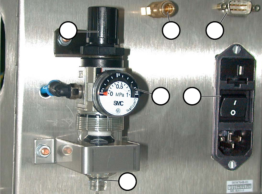
2.7 Pneumatic System Unit
It consists of a pressure reducer, pressure gauge and filter with container for condensed water.
The starting pressure is indicated on the pressure gauge (2 in Fig. 2.7 - 1). You can set it this pres-
sure by pulling it up and turning the cap (1). 2
Fig. 2.7 - 1 Back View with Pneumatic System Unit, etc.
(1) Cap of pressure reducer
(2) Pressure gauge
(3) Hand drain
(4) Compressed air connection
(5) CAN bus connection
(6) Main switch
2
2
1 4 5
62
3
External Power Supply Unit for the HS-50 / HS-60 / D4 Component Table User Manual
03/2006 Edition 2.8 Putting into Service
27
2.8 Putting into Service
2.9 Connecting
: Plug in the multifunction connector of the relevant component table (4 in Fig. 2.3 - 1) and lock
it in place with the clip.
: Optional: Plug the cable into the CAN bus connection (2 in Fig. 2.3 - 2).
: If this hasn’t been done already, fasten the quick release lock provided (5 in Fig. 2.2 - 1) prop-
erly on the compressed air supply hose.
: Plug the compressed air supply hose onto the compressed air connection (1 in Fig. 2.3 - 2).
: First turn off the main switch (6 in Fig. 2.7 - 1) and then plug in main cable into the unit.
2.9.1 Putting into Service
DANGER 2
: Before making the connection to the net, check whether the correct fuses are installed and
whether the correct voltage is set - depending on the main voltage available (see Chapter 2.5).
DANGER 2
: Make certain that no one is handling the connected component table when you turn on the
power.
2
: Turn the main switch on (6 in Fig. 2.7 - 1).
: There are 2 pilot lamps (2+3 in Fig. 2.3 - 1) on the front. The power is only available when both
lamps are lit.
: Lift the cap of the pressure reducer (1 in Fig. 2.7 - 1) and turn it until the pressure gauge (2 in
Fig. 2.7 - 1) indicates 250 kPa (turn clockwise to raise the pressure).