00191987-02.pdf - 第28页
User Manual External Power Supply Unit for the HS-50 / HS-60 / D4 Component Table 2.10 Maintenance 03/2006 Edition 28 2.10 Maintenance 2.10.1 Compressed Air Filter If the flo w rate decreases dr amatically , exch ange th…
External Power Supply Unit for the HS-50 / HS-60 / D4 Component Table User Manual
03/2006 Edition 2.8 Putting into Service
27
2.8 Putting into Service
2.9 Connecting
: Plug in the multifunction connector of the relevant component table (4 in Fig. 2.3 - 1) and lock
it in place with the clip.
: Optional: Plug the cable into the CAN bus connection (2 in Fig. 2.3 - 2).
: If this hasn’t been done already, fasten the quick release lock provided (5 in Fig. 2.2 - 1) prop-
erly on the compressed air supply hose.
: Plug the compressed air supply hose onto the compressed air connection (1 in Fig. 2.3 - 2).
: First turn off the main switch (6 in Fig. 2.7 - 1) and then plug in main cable into the unit.
2.9.1 Putting into Service
DANGER 2
: Before making the connection to the net, check whether the correct fuses are installed and
whether the correct voltage is set - depending on the main voltage available (see Chapter 2.5).
DANGER 2
: Make certain that no one is handling the connected component table when you turn on the
power.
2
: Turn the main switch on (6 in Fig. 2.7 - 1).
: There are 2 pilot lamps (2+3 in Fig. 2.3 - 1) on the front. The power is only available when both
lamps are lit.
: Lift the cap of the pressure reducer (1 in Fig. 2.7 - 1) and turn it until the pressure gauge (2 in
Fig. 2.7 - 1) indicates 250 kPa (turn clockwise to raise the pressure).
User Manual External Power Supply Unit for the HS-50 / HS-60 / D4 Component Table
2.10 Maintenance 03/2006 Edition
28
2.10 Maintenance
2.10.1 Compressed Air Filter
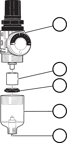
If the flow rate decreases dramatically, exchange the microfilter (2 in Fig. 2.10 - 1). Unlock the cou-
pling and pull it off the compressed air connection (1 in Fig. 2.3 - 2). Afterwards, screw the con-
tainer for condensed water (4 in Fig. 2.10 - 1) off the pressure reducer (1). After you tighten down
the little separating cap (3), you can remove the microfilter (2). 2
To install the new microfilter, perform the same steps in exactly reverse order. 2
Fig. 2.10 - 1 Compressed Air Filter Unit
2.10.2 Condensed Water
The transparent container for condensed water (4 in Fig. 2.10 - 1) must be emptied before the level
of the condensed water reaches the little separating cap (3). To do so, push the manual drain (5)
up. 2
2
2
01
0.5
SMC
MPa
5
10
0
2
3
4
5
1
(1) Pressure reducer
(2) Microfilter
(3) Little separating cap
(4) Container for condensed water
(5) Manual drain
External Power Supply Unit for the HS-50 / HS-60 / D4 Component Table User Manual
03/2006 Edition 2.11 Servicing Work If the Power Supply Unit Fails
29
2.11 Servicing Work If the Power Supply Unit Fails
2.11.1 Fuses on the outside of the device
DANGER 2
: Switch the device off and remove the power plug.
2
: If the power supply unit has failed, first check the two fuses in the power supply/connector com-
bination (Fig. 2.5 - 1) above the main switch.
: Release the snap lock on the fuse drawer and pull out the plastic insert with the two fuses.
: Check the two fuses and replace them if necessary.
2.11.2 Fuses inside the device
If neither of the two fuses in the power supply/connector combination is defective, it is also possi-
ble to check the fuses inside the device. 2
This step must only be carried out by a trained specialist, however. 2
DANGER 2
: Switch the device off and remove the power plug.
2
2
2
2
2
2