00193786-02.pdf - 第17页
S I P L A C E G EM S W V e r s i on G EM 505 . 03 SP 1 H O S T I n t e r f a c e M anua l ©S i e m en s A G, a ll r i gh t s r e s e r v ed page 17 o f 241 1 . 10 . 4 M ac h i n e A r eas o f a S I P L A C E S 25 M ac h …
SIPLACE GEM SW Version GEM 505.03 SP1 HOST Interface Manual
Page 16 of 241 ©Siemens AG, all rights reserved
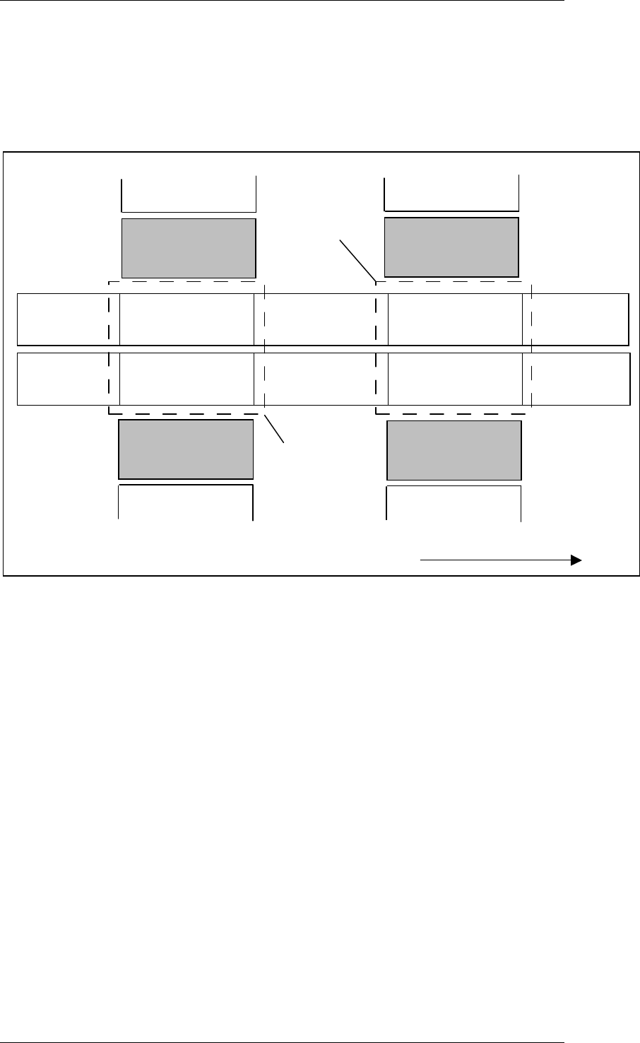
1.10.3 Machine Areas of a SIPLACE HS50 Machine
The figure below provides a diagrammatic overview of the individual areas of a
SIPLACE HS-50 placement station.
TWIN-Input
conveyor
TWIN-First
Processing
conveyor
TWIN-Output
conveyor
Input
conveyor
First Processing
conveyor
Output
conveyor
Direction of transport
Conveyor 2
(left)
Conveyor 1
(right)
Gantry 3
Head 3
Gantry 2
Head 2
Location
3
Location
2
TWIN-Inter-
mediate conveyor
TWIN-Second
Processing
conveyor
Intermediate
conveyor
Second Processing
conveyor
Gantry 4
Head 4
Location
4
Gantry 1
Head 1
Location
1
Processing 1
Area
Processing 2
Area
SIPLACE GEM SW Version GEM 505.03 SP1 HOST Interface Manual
©Siemens AG, all rights reserved page 17 of 241
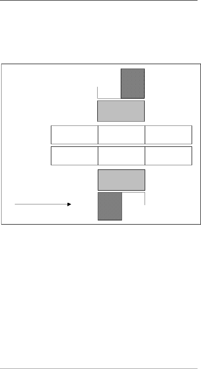
1.10.4 Machine Areas of a SIPLACE S25 Machine
The layout of the feeder locations of the S25 machine depends on the configuration of
the individual machine. If there is an MTC on one side of the machine, the locations are
divided. Otherwise they are grouped into one location. The following figures illustrate the
individual variants.
The figures shows the machine areas of an S25 with dual conveyor and 2 MTCs.
The conveyor belts are divided into 3 areas. There are 4 feeder locations.
TWIN-Input
conveyor
TWIN-First
Processing
conveyor
TWIN-Output
conveyor
Input
conveyor
First Processing
conveyor
Output
conveyor
Direction of transport
Conveyor 2 (left)
Conveyor 1
(right)
Gantry 1
Revolverhead 1
Gantry 2
Revolverhead 2
Location
3
MTC
Location
4
Location
2
Location
1
MTC
SIPLACE GEM SW Version GEM 505.03 SP1 HOST Interface Manual
Page 18 of 241 ©Siemens AG, all rights reserved
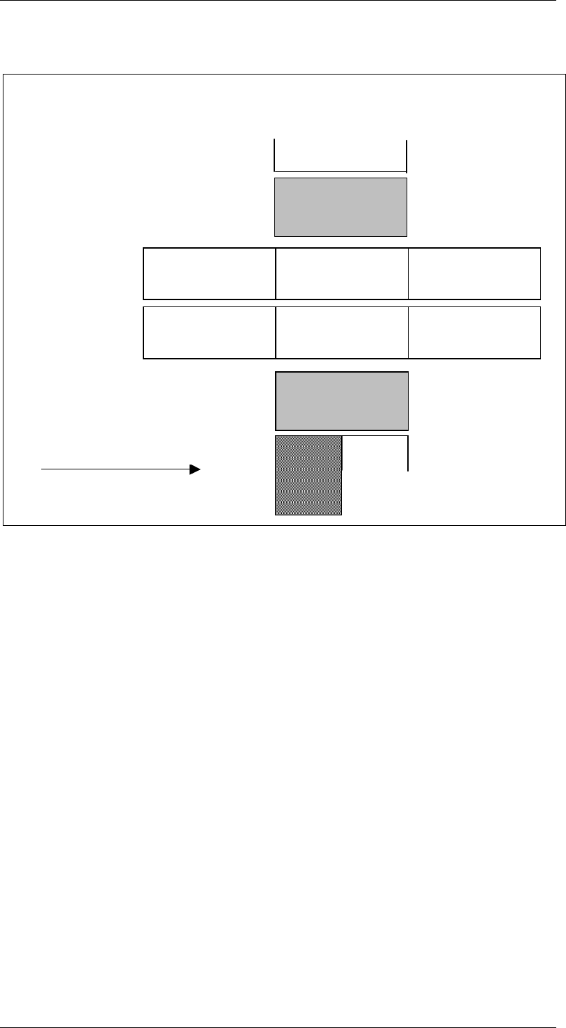
This figure shows an S25 machine with 1 MTC.
If the machine has only 1 MTC, there is one divided feeder location and one undivided
feeder location. The MTC can be on location 1 or 3.
If the MTC is on location 1, locations 1 and 2 are on the RH side and there is a shared
feeder location on the LH side (see illustration).
If the MTC is on the LH side, locations 3 (MTC) and 4 are on the LH side and a there is a
shared location 1 on the RH side.
TWIN-Input
conveyor
TWIN-First
Processing
conveyor
TWIN-Output
conveyor
Input
conveyor
First Processing
conveyor
Output
conveyor
Direction of transport
Conveyor 2 (left)
Conveyor 1
(right)
Gantry 1
Revolverhead 1
Gantry 2
Revolverhead 2
Location
3
Location
2
Location
1
MTC