00193786-02.pdf - 第21页
S I P L A C E G EM S W V e r s i on G EM 505 . 03 SP 1 H O S T I n t e r f a c e M anua l ©S i e m en s A G, a ll r i gh t s r e s e r v ed page 21 o f 241 2 M essa g e S u mm a r y 2 . 1 H o st t o E qu i p m e n t T h …

SIPLACE GEM SW Version GEM 505.03 SP1 HOST Interface Manual
Page 20 of 241 ©Siemens AG, all rights reserved
1.11 State Diagrams{XE „State Diagrams“}
This document uses several Finite State Machine diagrams to describe the current
condition of the Equipment’s SECS link, material handling mechanisms, and process
cycle. Each Finite State Machine diagram includes a State Diagram and a complete
description of the states and state transitions.
All Finite State Diagrams have been prepared in the format specified in the GEM
standard. This notation is required as a fundamental part of GEM compliance and must
be included in the Equipment SECS Interface Documentation. This notation is the
„Statechart“ notation developed by David Harel.
The following are the major characteristics of this notation as it is used in this document:
Each state is represented by a rectangle with rounded corners.
A collection of sub-states may be grouped into a super-state.
The entity described by the diagrams will be in one and only one of the sub-states at all
times.
Variables representing the current state of an entity do not contain values for super-
states, only the lowest sub-state is represented.
State transitions are represented by single-headed arrows.
Each state transition is a Collection Event, and it has a unique Collection Event ID
(CEID)
An arrow directly from a super-state to another state describes a Collection Event that
can occur while the entity is in any one of the sub-states contained in the super-state.
An arrow directly into a super-state to the H* (history) symbol describes a transition to the
lowest sub-state which described the entity just before the transition out of the super-
state.
An arrow directly into a super-state to the C (conditional) symbol describes a transition to
a particular sub-state based on some other relevant data. The conditional data is not
represented in the diagram but is described in the associated text.
SIPLACE GEM SW Version GEM 505.03 SP1 HOST Interface Manual
©Siemens AG, all rights reserved page 21 of 241
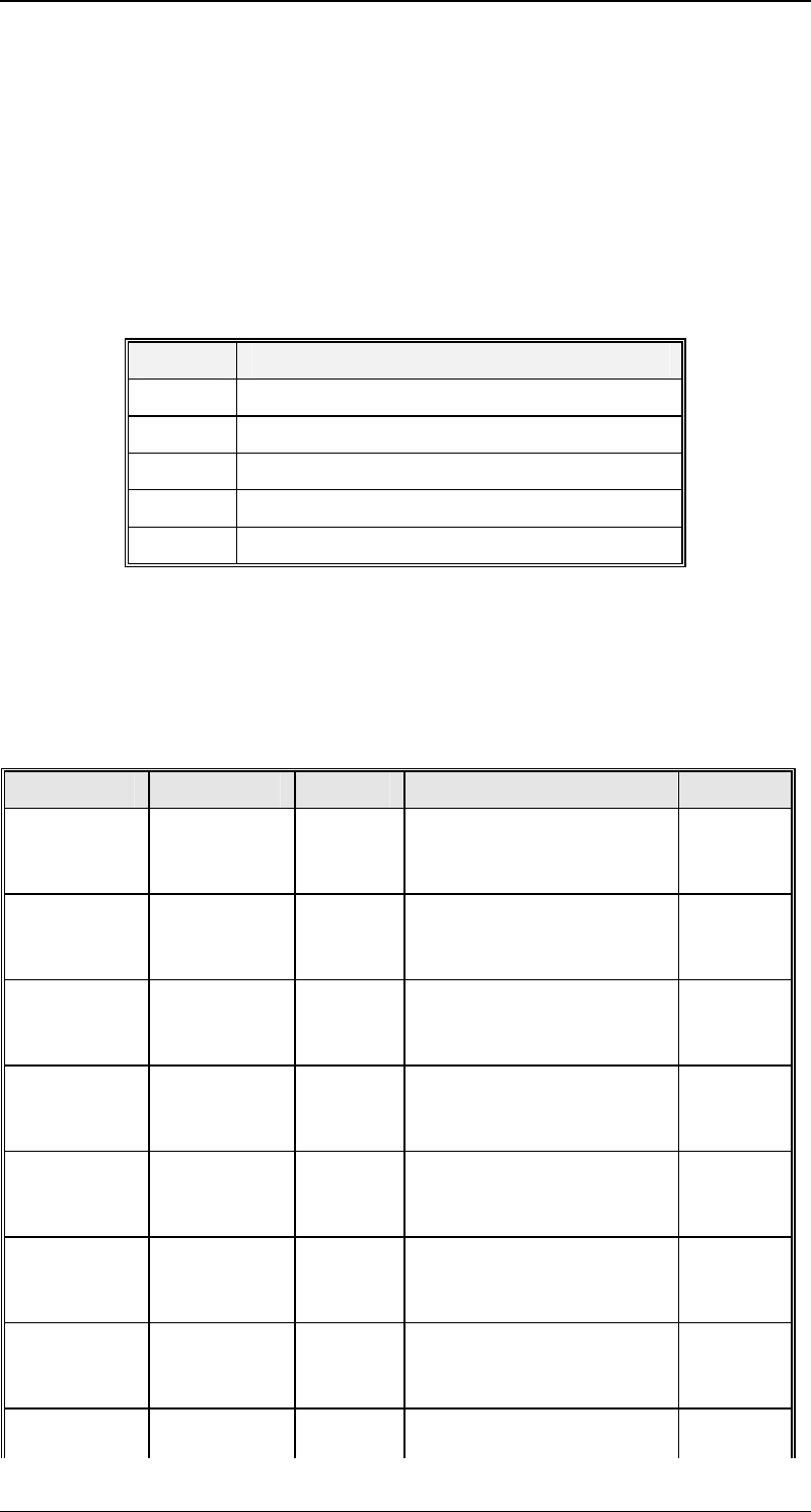
2 Message Summary
2.1 Host to Equipment
This section describes primary SECS messages sent by the Host, and the associated
reply messages from the Equipment.
The column headed "CState" in the table below indicates the control state the Equipment
must be in to accept the message. The current value of the Equipment Control State
can be found in variable {XE "CONTROLSTATE "}CONTROLSTATE (vid 1002006).
Possible values for this column are as follows:
Value State
1 Off-Line/Equipment Off-Line
2 Off-Line/Attempt On-Line
3 Off-Line/Host Off-Line
4 On-Line/Local
5 On-Line/Remote
Unlawful messages sent to the Equipment while Control State is Off-Line (1, 2, or 3) will
be replied to with a SnF0 message. Thus, the Host will only ever see values of 4 or 5 for
CONTROLSTATE.
In the column headed "Notes", those messages marked with "E" are extensions beyond
GEM. Those messages marked with "N" are provided for non-GEM or older GEM
compatibility.
Primary Reply CState Description Notes
{XE
"S1F1"}S1F
1
{XE
"S1F2"}S1F
2
4,5 Are You There
{XE
"S1F3"}S1F
3
{XE
"S1F4"}S1F
4
4,5 Selected Status
{XE
"S1F11"}S1
F11
{XE
"S1F12"}S1
F12
4,5 Status Variable Namelist
Request
{XE
"S1F13"}S1
F13
{XE
"S1F14"}S1
F14
All Connect Request
{XE
"S1F15"}S1
F15
{XE
"S1F16"}S1
F16
4,5 Request Off-Line
{XE
"S1F17"}S1
F17
{XE
"S1F18"}S1
F18
1,2,3 Request On-Line
{XE
"S1F65"}S1
F65
{XE
"S1F66"}S1
F66
All Connect Request N
{XE
"S2F13"}S2
{XE
"S2F14"}S2
4,5 Equipment Constant
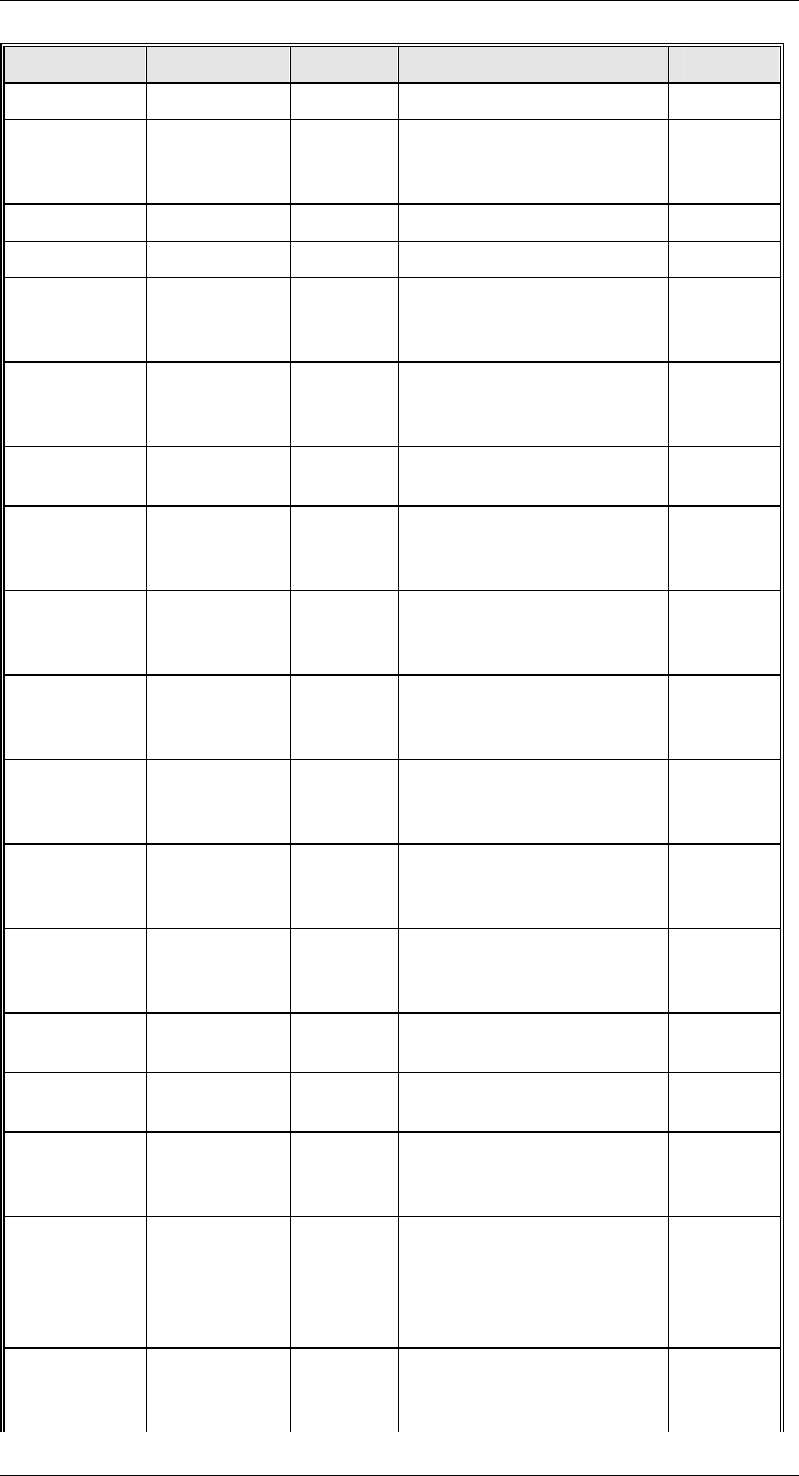
SIPLACE GEM SW Version GEM 505.03 SP1 HOST Interface Manual
Page 22 of 241 ©Siemens AG, all rights reserved
Primary Reply CState Description Notes
F13 F14 Request
{XE
"S2F15"}S2
F15
{XE
"S2F16"}S2
F16
4,5 New Equipment Constant
Send
S2F17 S2F18 4,5 Date and Time Request
S2F21 S2F22 5 Remote Command N
{XE
"S2F23"}S2
F23
{XE
"S2F24"}S2
F24
4,5 Trace Initialize
{XE
"S2F25"}S2
F25
{XE
"S2F26"}S2
F26
4,5 Loopback Diagnostic E
S2F27 S2F28 5 Initiate Processing
Request
N
{XE
"S2F29"}S2
F29
{XE
"S2F30"}S2
F30
4,5 Equipment Constant
Namelist Request
E
{XE
"S2F31"}S2
F31
{XE
"S2F32"}S2
F32
4,5 Date and Time Send
{XE
"S2F33"}S2
F33
{XE
"S2F34"}S2
F34
4,5 Define Report
{XE
"S2F35"}S2
F35
{XE
"S2F36"}S2
F36
4,5 Link Event Report
{XE
"S2F37"}S2
F37
{XE
"S2F38"}S2
F38
4,5 Enable/Disable Event
Report
{XE
"S2F39"}S2
F39
{XE
"S2F40"}S2
F40
4,5 Multi-Block Inquire/Grant
S2F41 S2F42 (4),5 Remote Command with
Parameters
S2F43 S2F44 4,5 Reset Spooling Streams
and Functions
{XE
"S2F45"}S2
F45
{XE
"S2F46"}S2
F46
4,5 Define Variable Limits
Attributes
{XE
"S2F41"}{X
E
"S2F47"}S2
F47
{XE
"S2F42"}{X
E
"S2F48"}S2
F48
4,5 Variable Limit Attribute
Request
{XE
"S5F3"}S5F
3
{XE
"S5F4"}S5F
4
4,5 Enable/Disable Alarm