00193786-02.pdf - 第37页
S I P L A C E G EM S W V e r s i on G EM 505 . 03 SP 1 H O S T I n t e r f a c e M anua l ©S i e m en s A G, a ll r i gh t s r e s e r v ed page 37 o f 241 3 . 3 P r o cess S tates T he Pr o c e ss S t a t e D i ag r a m…

SIPLACE GEM SW Version GEM 505.03 SP1 HOST Interface Manual
Page 36 of 241 ©Siemens AG, all rights reserved
Variable Name VID
{XE
„INITCONTROLSTATE“}INITCONTROLSTA
TE
1002005
{XE
„OFFLINESUBSTATE“}OFFLINESUBSTAT
E
1002010
{XE „ONLINEFAILED“}ONLINEFAILED
1002008
{XE
„ONLINESUBSTATE“}ONLINESUBSTATE
1002009
{XE „CONTROLSTATE“}CONTROLSTATE
1002006
{XE
„PREVIOUSCONTROLSTATE“}PREVIOUS
CONTROLSTATE
1002007
3.2.5 Related Events
The following lists the collection events (CEIDs) which are relevant to the Control State.
For a more complete description of these events, see "Appendix B -- Collection Events"
or the description in this chapter.
Collection Event CEID
{XE
„GemControlStateLOCAL“}GemControlState
LOCAL
1000003
{XE
„GemControlStateREMOTE“}GemControlSt
ateREMOTE
1000004
{XE
„GemEquipmentOFFLINE“}GemEquipment
OFFLINE
1000005
3.2.6 Restriction
Only RemoteStart and RemoteStop are available in this stage. Other Remote
Commands will be available in a later version.
SIPLACE GEM SW Version GEM 505.03 SP1 HOST Interface Manual
©Siemens AG, all rights reserved page 37 of 241
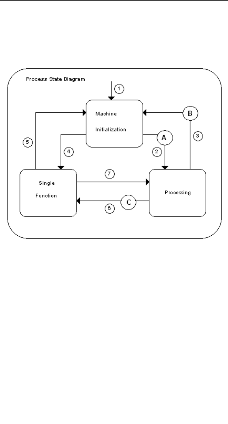
3.3 Process States
The Process State Diagram illustrates in detail the processing at the SIPLACE.
In some state transitions there will be an intermediate state (A, B, C) for a short time (see
charpter intermediate states).

SIPLACE GEM SW Version GEM 505.03 SP1 HOST Interface Manual
Page 38 of 241 ©Siemens AG, all rights reserved
3.3.1 SIPLACE Process State Transitions
# From Trigger To Description
1 Unknown Power-Up Machine
Initialization
At power-up, the
Equipment defaults to the
Machine initialization state.
2 Machine
Initialization
Machine is
ready
Processing All data is available to
produce a board. All
peripheral equipment like
the Vision system is
initialized and the machine
has finished the reference
runs correctly. In this state
the machine will start its
work, when a PCB is put on
the input conveyor
3 Processing new Data from
the Host
Machine
Initialization
New production data is sent
while the machine is
processing a board. The
board will be finished and
the machine will go to the
Machine initialization state
4 Machine
Initialization
a) Fatal Error
during machine
initialization
b) Stop-Button
on GUI
Single
Function
When a fatal error occurs
during machine
initialization it will
automatically switch to
single function mode.
In the case that the
operator presses the Stop-
Button on the GUI, the
machine will first end the
board in the center
conveyor (if there is one)
and will then enter the
single function mode.
5 Single
Function
Start-Button on
GUI
Machine
Initialization
When the machine is in
single function mode, the
operator press the Start-
button and the Prestate
was machine Initialization
the machine will return to
the Machine initialization
state.
6 Processing a) Fatal Error
during machine
initialization
b) Stop-Button
on GUI
Single
Function
When a fatal error occurs
during processing the
machine will automatically
switch to single function
mode.
In the case that the
operator press the Stop-
Button on the GUI, the
machine will first end the
board in the center
conveyor (if there is one)
and will then enter the