JUKI FX-3R MAINTENANCE GUIDE.pdf - 第97页
FX-3R Maintenance Guide 8-15 8-3-3. Replacing the Bank PCB 1) Remove the mounting bolts (hexagon socket head cap bolt with washer, M3 L=8) to detach the front panel. 2) Disconnect the connectors (cables) from the electri…
FX-3R Maintenance Guide
8-14
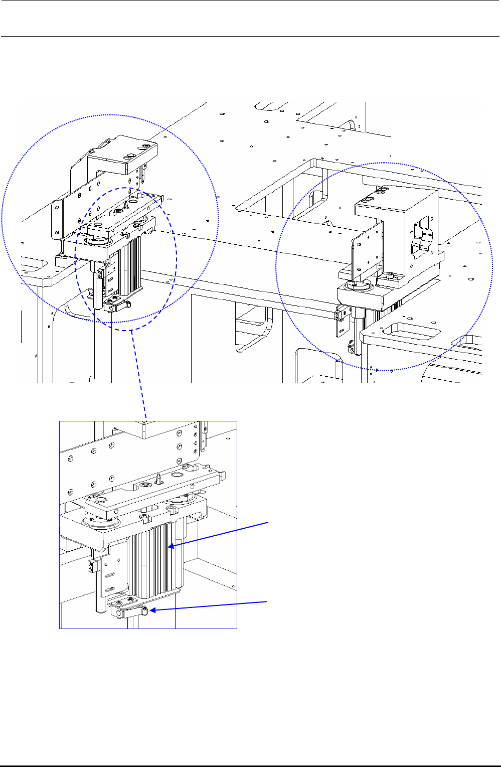
8-3-2. Overall Drawing (Lifter Unit)
40063873
Lifter LL assembly
40063872
Lifter LR assembly
PA630850100
Air cylinder
PV010505000
Mechanical valve
Figure 8-3-2-1 Overall drawing (Lifter Unit)
Rev. 1.00
FX-3R Maintenance Guide
8-15
8-3-3. Replacing the Bank PCB
1) Remove the mounting bolts (hexagon socket head cap bolt with washer, M3 L=8) to detach the
front panel.
2) Disconnect the connectors (cables) from the electric bank PCB.
3) Remove the PCB mounting screws (round head screw with washer, M3 L=8) to replace the
PCB.
4) Reassemble the components in the reverse order of disassembly.
40084914
Bank PCB box assembly
SL6030892TN
Hexagon socket head
cap bolt with washer
M3 L=8
40047311
Front panel
SL4030881SC
Round head screw
with washer M3 L=8
40047552
Electric bank PCB
assembly
Figure 8-3-3-1 Bank PCB Box
Rev. 1.00
FX-3R Maintenance Guide
8-16
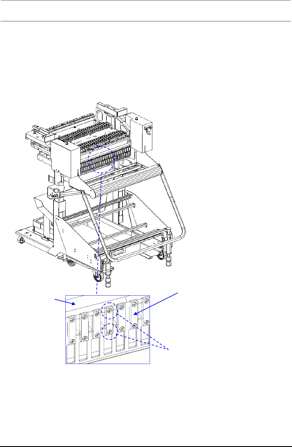
8-3-4. Replacing the Connector Cable
1) Remove the connector mounting screws to detach the connector from the FDC bracket.
2) Detach the front panel. (See Figure 8-3-3.)
3) Disconnect the connectors from the electric bank PCB and replace the cables.
4) Reassemble the components in the reverse order of disassembly.
40084636
FDC bracket
40084826 - EF IF CBL 1-5 ASM
40084827 - EF IF CBL 6-10 ASM
40084828 - EF IF CBL 11-15 ASM
40084829 - EF IF CBL 16-20 ASM
40084830 - EF IF CBL 21-25 ASM
40084831 - EF IF CBL 26-30 ASM
HK079190000
Connector screw
Figure 8-3-4-1 Replacement of Connector Cable
Rev. 1.00