JUKI FX-3R MAINTENANCE GUIDE.pdf - 第104页
FX-3R Maintenance Guide 8-22 40095349 Bank PCB box assembly (EO) Figure 8-4-1-2 Overall Drawing (Fro m Obliquely downward View Field) Rev. 1.00
FX-3R Maintenance Guide
8-21
8-4. Electric Fixed Bank (Optional)
DANGER
To prevent any trouble caused by accidental machine start, always
shut-down the power before starting the maintenance and
adjustment work.
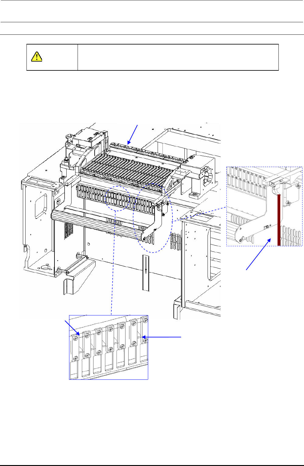
8-4-1. Overall Drawing
40084841
EF setup cable 1 bracket
assembly
40089564
FDC bracket
40095345
Fixed bank unit for ETF
40084826 - EF IF CBL 1-5 ASM
40084827 - EF IF CBL 6-10 ASM
40084828 - EF IF CBL 11-15 ASM
40084829 - EF IF CBL 16-20 ASM
40084830 - EF IF CBL 21-25 ASM
40084831 - EF IF CBL 26-30 ASM
Figure 8-4-1-1 Overall Drawing
Rev. 1.00
FX-3R Maintenance Guide
8-22
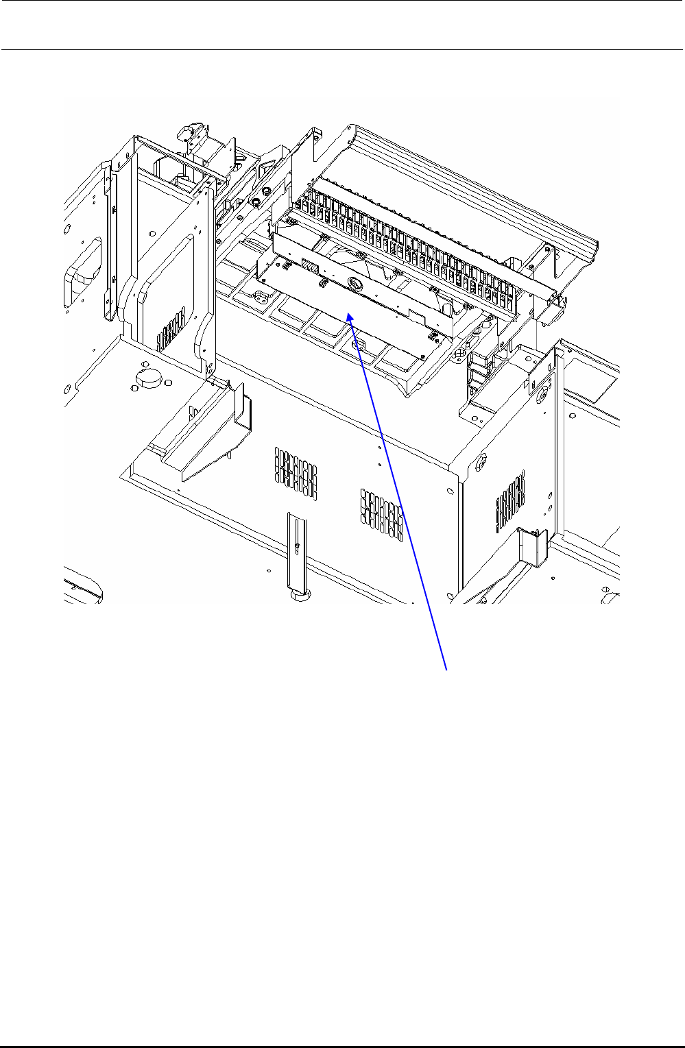
40095349
Bank PCB box assembly (EO)
Figure 8-4-1-2 Overall Drawing (From Obliquely downward View Field)
Rev. 1.00
FX-3R Maintenance Guide
8-23
8-4-2. Replacing the Outer Bank PCB and Connector Cable
The bank PCB and connector cable are replaced in the same manner as described for the
replacement table for ETF. To do so, see the sections below.
1) Replacing the bank PCB → 8-3-3
2) Replacing the connector cable → 8-3-4
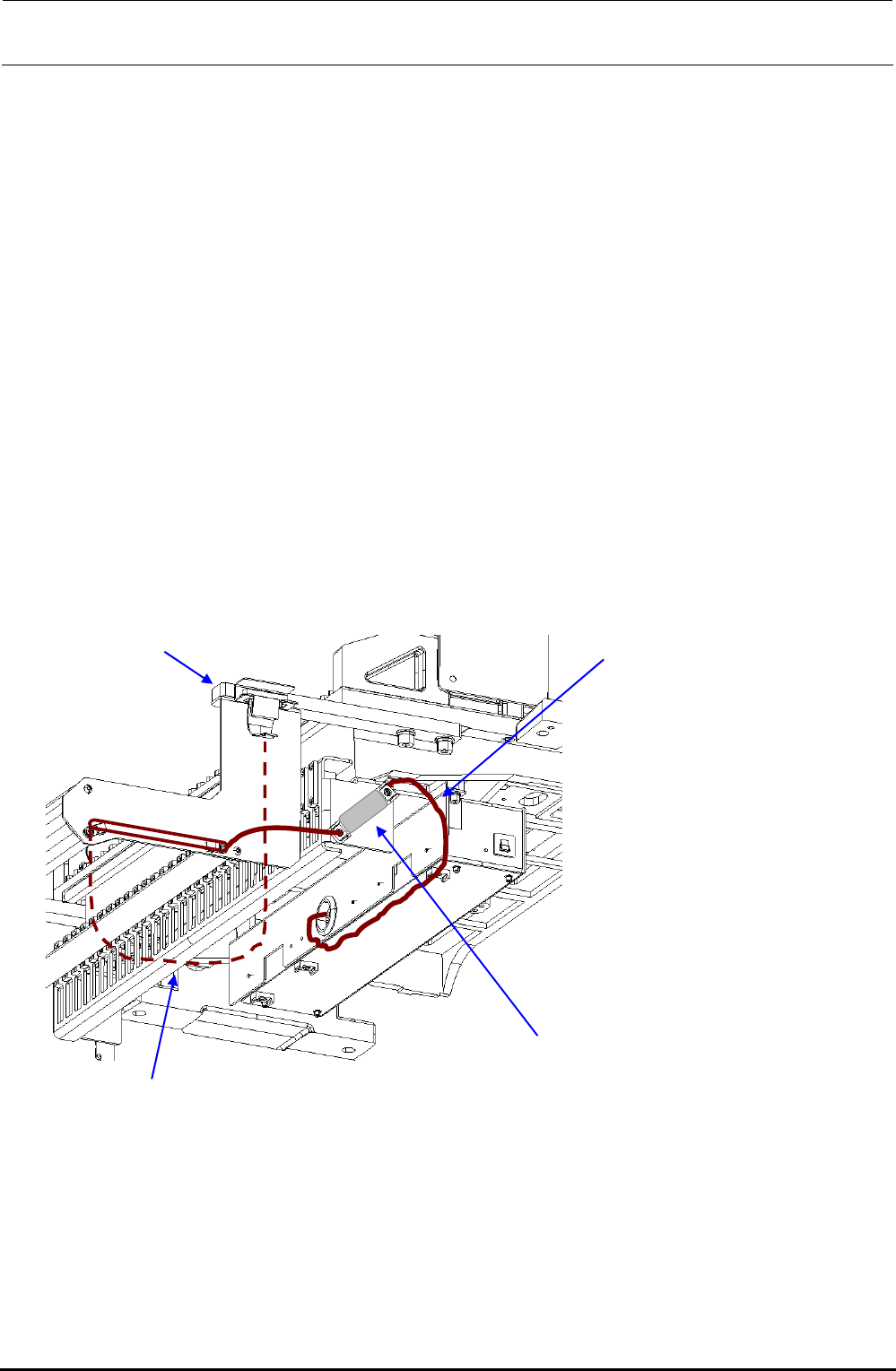
8-4-3. Replacing the Connector for Off-line Setup
1) Disconnect the connector for the off-line setup from the E trolley cover R.
2) Disconnect the connector connecting the cable of the connector for the off-line setup and the
relay cable to the electric bank PCB (right side surface of FDC bracket). After that, replace the
connector for the off-line setup.
3) Reassemble the components in the reverse order of disassembly.
4009
Rev. 1.00
40084837
EF setup cable 2 assembly
Connect the connector on the side
surface of the FDC bracket.
5351
e stay
40084841
EF setup cable 1 bracket assembly
∗ Adjust the length of the dotted portion to 650 mm.
Tape guid
8-4-4. Replacing the ETF Incorrect Insertion Detection Sensor
For details, see section 8-3-6, Replacing the ETF Incorrect Insertion Detection Sensor
(Replacement Table for Electric Feeder).