JUKI FX-3R MAINTENANCE GUIDE.pdf - 第119页
FX-3R Maintenance Guide 10-4 10-3-2. Operation Key 1) Remo ve two mounting screws c to replace the SAFETY_SWITCH_KEY d . SL6041042TN SEMS cap bolt with washer M4 × 10 SAFETY_SWITCH_KEY Figure 10-3-2-1 Operation Key Rev. …
FX-3R Maintenance Guide
10-3
10-3. Replacing the Cover Open Switch
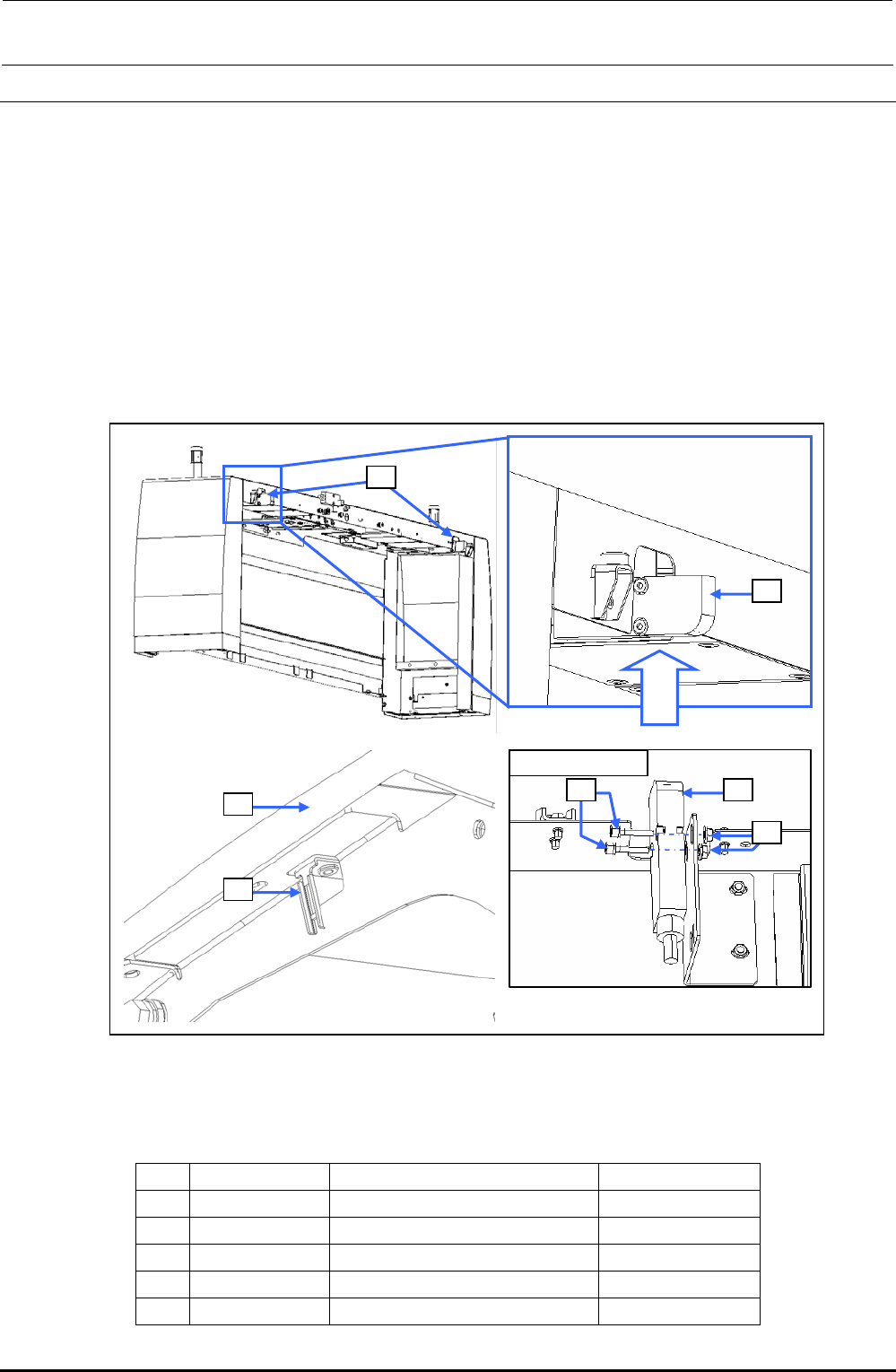
10-3-1. Switch Main Unit
1) Disconnect the connector of the switch c from the relay connector.
2) Cut the tie-up band and remove the set screws d (SL6042042TN) to replace the switch c
main unit.
3) Reassemble the components in the reverse order of disassembly.
After assembling, check to make sure that the assembly has been fit in the safety cover f, and
the operation key can be inserted into the switch properly.
∗ After the new switch has been mounted, make sure that the safety cover f is mounted
correctly and that the operation key g is inserted into the switch correctly.
Rev. 1.00
Viewed from A
c
c
d c
e
f
g
Viewed
from A
Figure 10-3-1 Replacing the Switch Main Unit
[List of Replacement Parts]
Table 10-3-1 Replacement Parts for Cover Open Switch
No. Part No. Part name Q’ty per machine
c
40002254 COVER_OPEN_SW_CABLE_ASM 8
d
SL6042042TN SEMS cap bolt 16
e
NM3040520SF Nut 16
f
40063507 SAFETY_COVER_FRAME 4
g
HA005280010 SAFTY_SWITCH_KEY 8
FX-3R Maintenance Guide
10-4
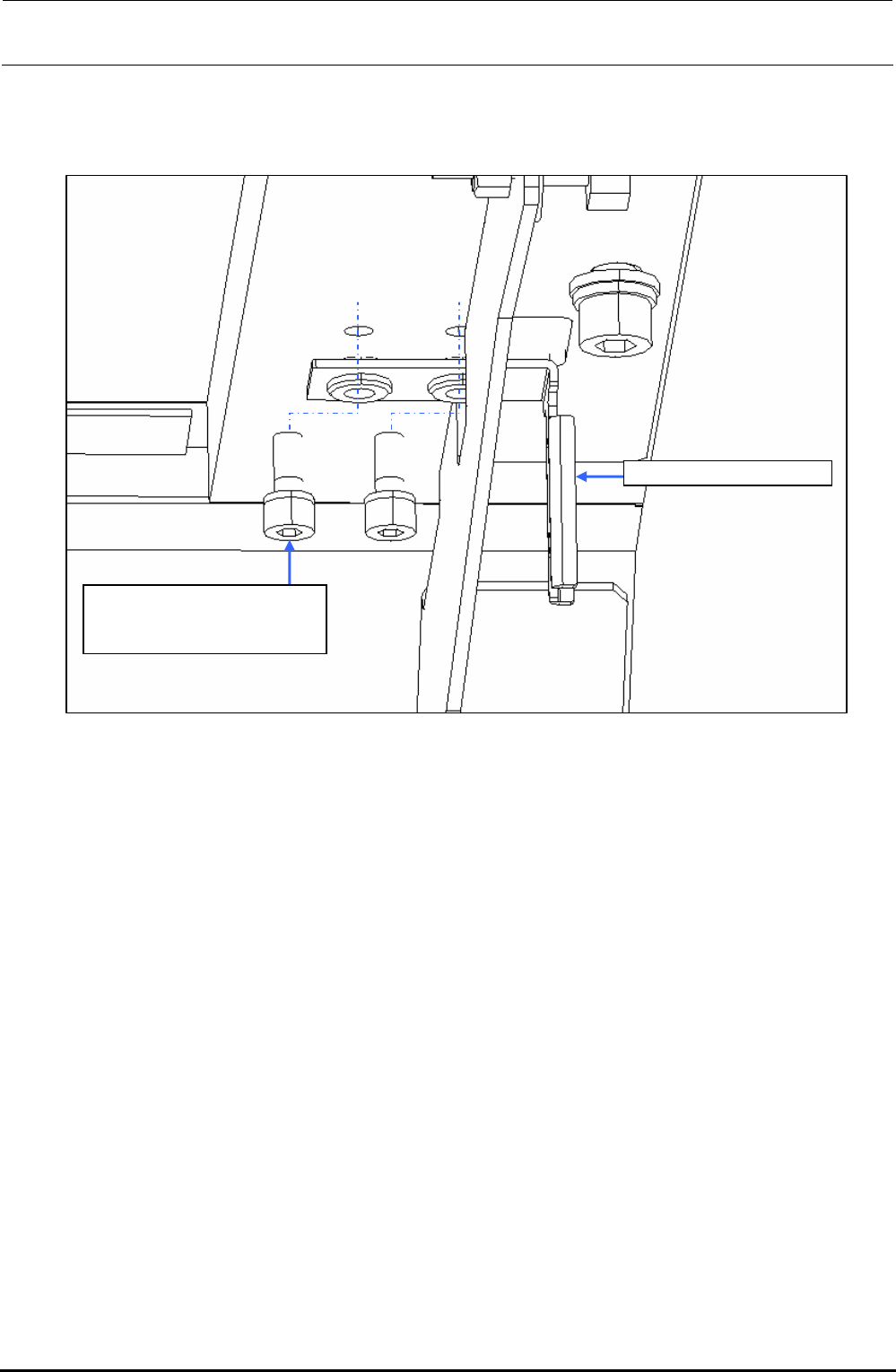
10-3-2. Operation Key
1) Remove two mounting screws c to replace the SAFETY_SWITCH_KEY d.
SL6041042TN
SEMS cap bolt with washer
M4×10
SAFETY_SWITCH_KEY
Figure 10-3-2-1 Operation Key
Rev. 1.00

FX-3R Maintenance Guide
10-5
10-4. Replacing the Push-Button Switch (CE Marking Machine)
On-line switch Start switch
Keyboard
setting switch
Origin return
switch
Stop
switch
Single cycle
switch
Maintenance
key switch
Figure 10-4-1 Switch Names on Front Operation Panel
Start switch
Keyboard
setting switch
Stop
switch
Single cycle
switch
Figure 10-4-2 Switch Names on Rear Operation Panel
Rev. 1.00