JUKI FX-3R MAINTENANCE GUIDE.pdf - 第124页
FX-3R Maintenance Guide 11-3 Rev. 1.00 e FSD bracket assembly (rear left portion) Figure 11-4 FSD Bracket Assembly (Rear Left Portion) f FSD bracket assembly (rear right portion) Figure 11-5 FSD Bracket Assembly (Rear Ri…
FX-3R Maintenance Guide
11-2
Rev. 1.00
2) Replace the sensor in the detached bracket assembly with a new one.
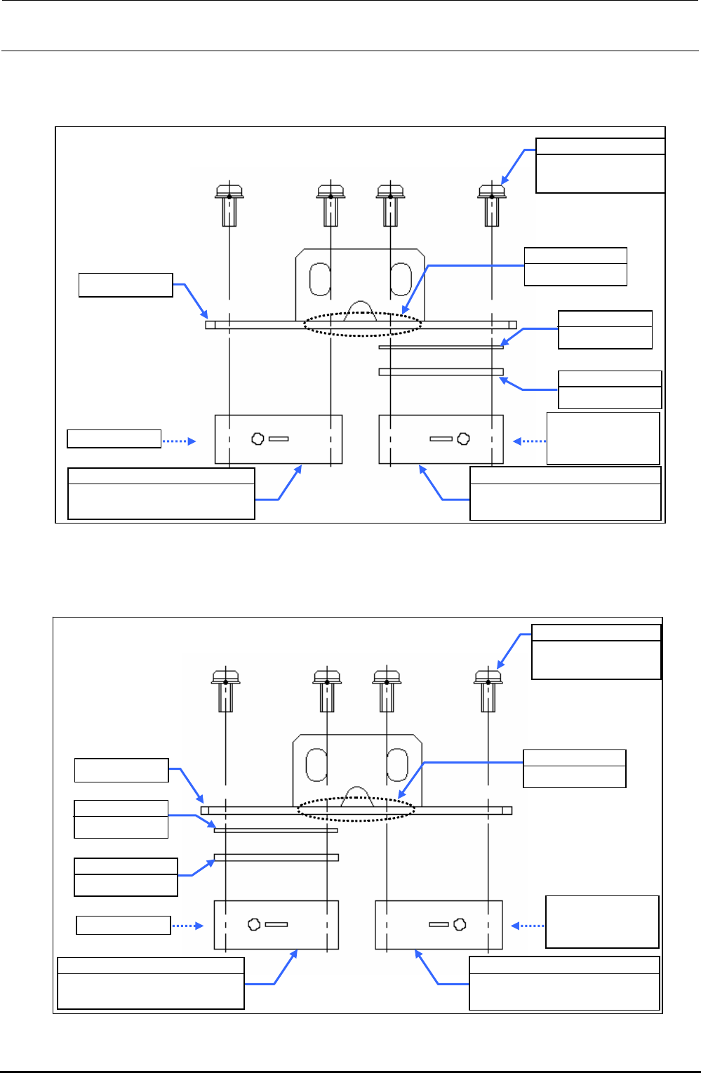
c FSD bracket assembly (front left portion)
Figure 11-2 FSD Bracket Assembly (Front Left Portion)
d FSD bracket assembly (front right portion)
Figure 11-3 FSD Bracket Assembly (Front Right Portion)
SL4031481SC
SEMS cap bolt
M3×14
EA9500B0100
Tie-up band
Sensitivity
adjustment side
of check LED
40047495
Feeder float sensor (FF)
light emission assembly
FSD bracket
40001312
OCC shim C
E2157729000
FSD spacer
Check LED
40047498
Feeder float sensor (FR)
light receiving assembly
FSD bracket
SL4031481SC
SEMS cap bolt
M3×14
E2157729000
FSD spacer
40047496
Feeder float sensor (FF)
light receiving assembly
EA9500B0100
Tie-up band
Check LED
Sensitivity
adjustment side
of check LED
40001312
OCC shim C
40047497
Feeder float sensor (FR)
light emission assembly
FX-3R Maintenance Guide
11-3
Rev. 1.00
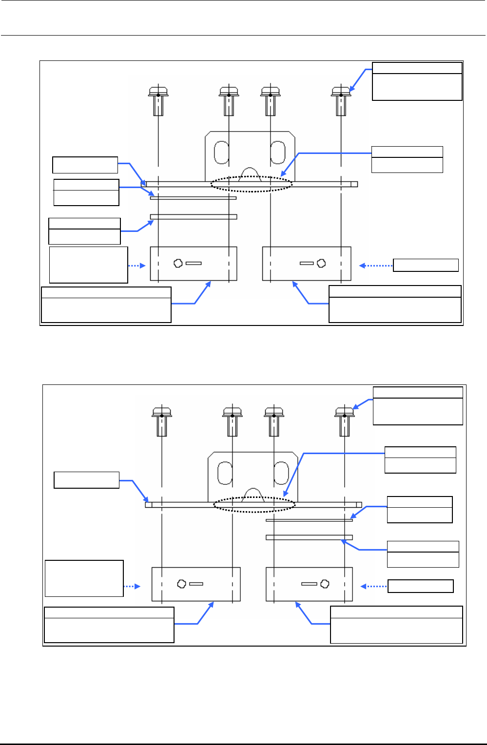
e FSD bracket assembly (rear left portion)
Figure 11-4 FSD Bracket Assembly (Rear Left Portion)
f FSD bracket assembly (rear right portion)
Figure 11-5 FSD Bracket Assembly (Rear Right Portion)
SL4031481SC
SEMS cap bolt
M3×14
EA9500B0100
Tie-up band
Sensitivity
adjustment side
of check LED
40070400
Feeder float sensor (RR)
light receiving assembly
FSD bracket
40001312
OCC shim C
E2157729000
FSD spacer
Check LED
40070397
Feeder float sensor (RF)
light emission assembly
SL4031481SC
SEMS cap bolt
M3×14
EA9500B0100
Tie-up band
40001312
OCC shim C
E2157729000
FSD spacer
Check LED
FSD bracket
Sensitivity
adjustment side
of check LED
40070399
Feeder float sensor (RR)
light emission assembly
40070398
Feeder float sensor (RF)
light receiving assembly
FX-3R Maintenance Guide
11-4
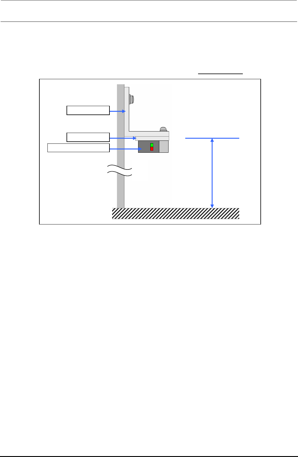
3) Adjust the height of a newly mounted sensor.
Adjust the height of the top surface of the FSD bracket to 126.6±0.1 mm from the top surface of
the feeder bank, and secure it.
However, adjust the height of the FSD bracket with a set of left and right sensors (light
receiving and light emission) so that a difference in height is
0.1 mm or less.
FSD bracket
FSD spacer
Feeder float spacer
126.6 ± 0.1mm
Figure 11-6 Adjusting the Height of the Feeder Float Sensor
4) Adjust the light axis.
c Connect the connectors of the sensors to their specified positions and turn on the power to
the main unit.
d Move the light emission and light receiving sensors so that the light axis is matched.
When the light axis is adjusted correctly, both the red and green LEDs on the light receiving
sensor will light up.
(The red LED is the operation indicator lamp and the green LED is the stability indicator
lamp.)
∗ For the FSD bracket assembly, adjust the light axis of two sensors.
Rev. 1.00