JUKI FX-3R MAINTENANCE GUIDE.pdf - 第134页
FX-3R Maintenance Guide 12-5 12-2-1-2. Replacing the SSD The SSD is installed on the control support. 1) Remove the SEMS cap bolts to detach the overall SSD from the bracket while carefully checking the IDE connector s…
FX-3R Maintenance Guide
12-4
Rev. 1.00
12-2. Replacing the System Disk
In the FX-3R, the system disk consists of one large capacity SSD and its inside is partitioned to C
drive and D drive. The C drive contains Windows or operating system, such as RTX. The D drive
contains the FX-3R system programs, parameters, and production program files.
12-2-1. Replacing the SSD
The SSD contains Windows or operating system, such as RTX necessary to operate the
FX-3R-series.
You must always follow the instructions described in this manual when replacing the SSD.
12-2-1-1. Required Components
ENVIROMENT SYSTEM 132 ASM (SSD)
FX-3R needs the ENVIRONMENT SYSTEM 132 ASM (SSD that contains the OS
environment including Windows and RTX necessary to operate the machine).
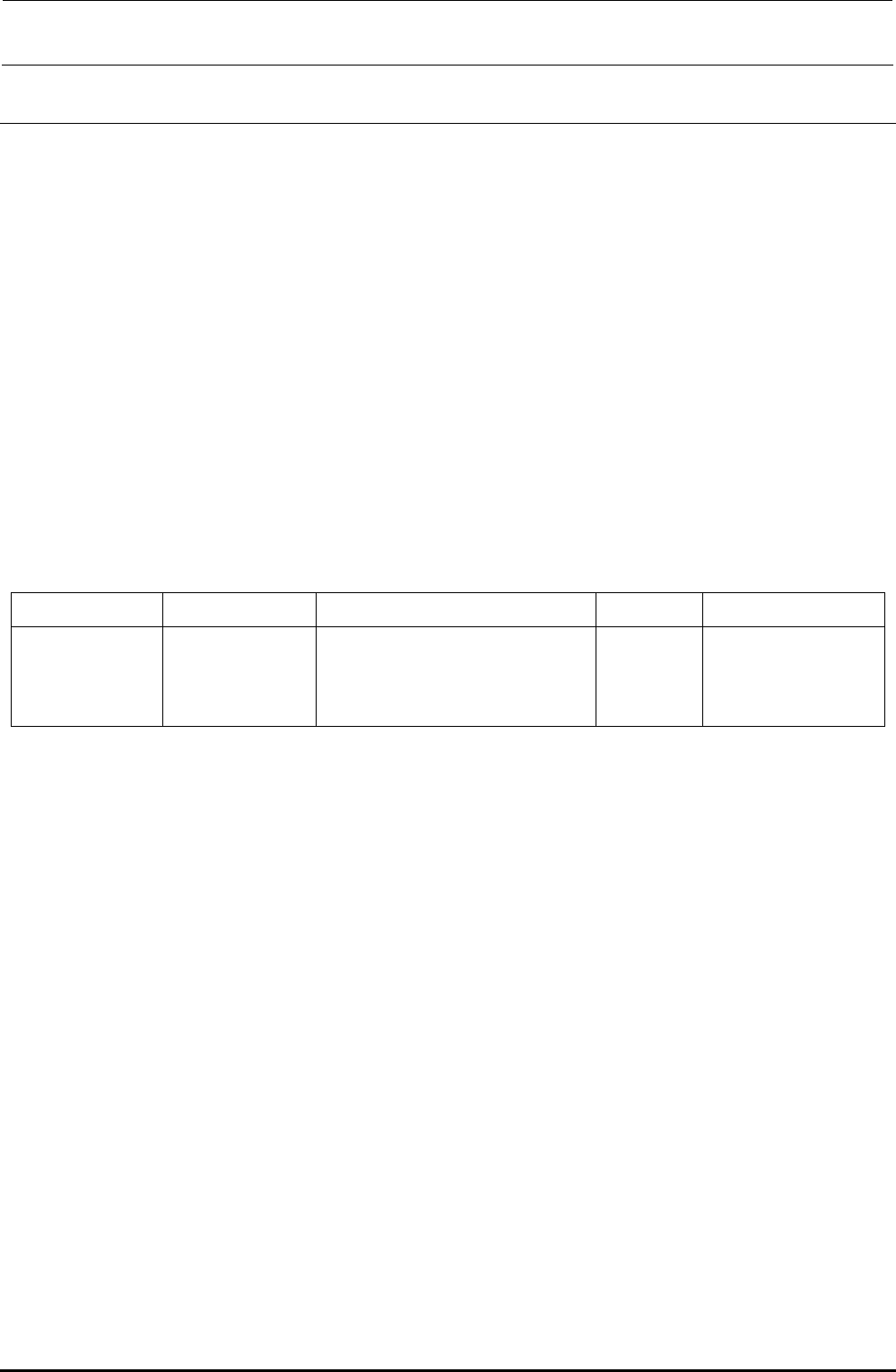
Table 12-2-1-1-1 SSD Part No.
Language OS Part name Part No. Remarks
Common
(Japanese, English,
and Chinese)
WindowsXP Emb ENVIROMENT SYSTEM 132 ASM 40109193
FX-3R system program installation disk
The system program installation disk contains the software designed for the FX-3R. All
system programs for the FX-3R are saved into this disk. When installing the system programs,
it is necessary to specify a model (only when installing the system programs newly).
Flexline DB installation disk: Component library database
FX-3R Maintenance Guide
12-5
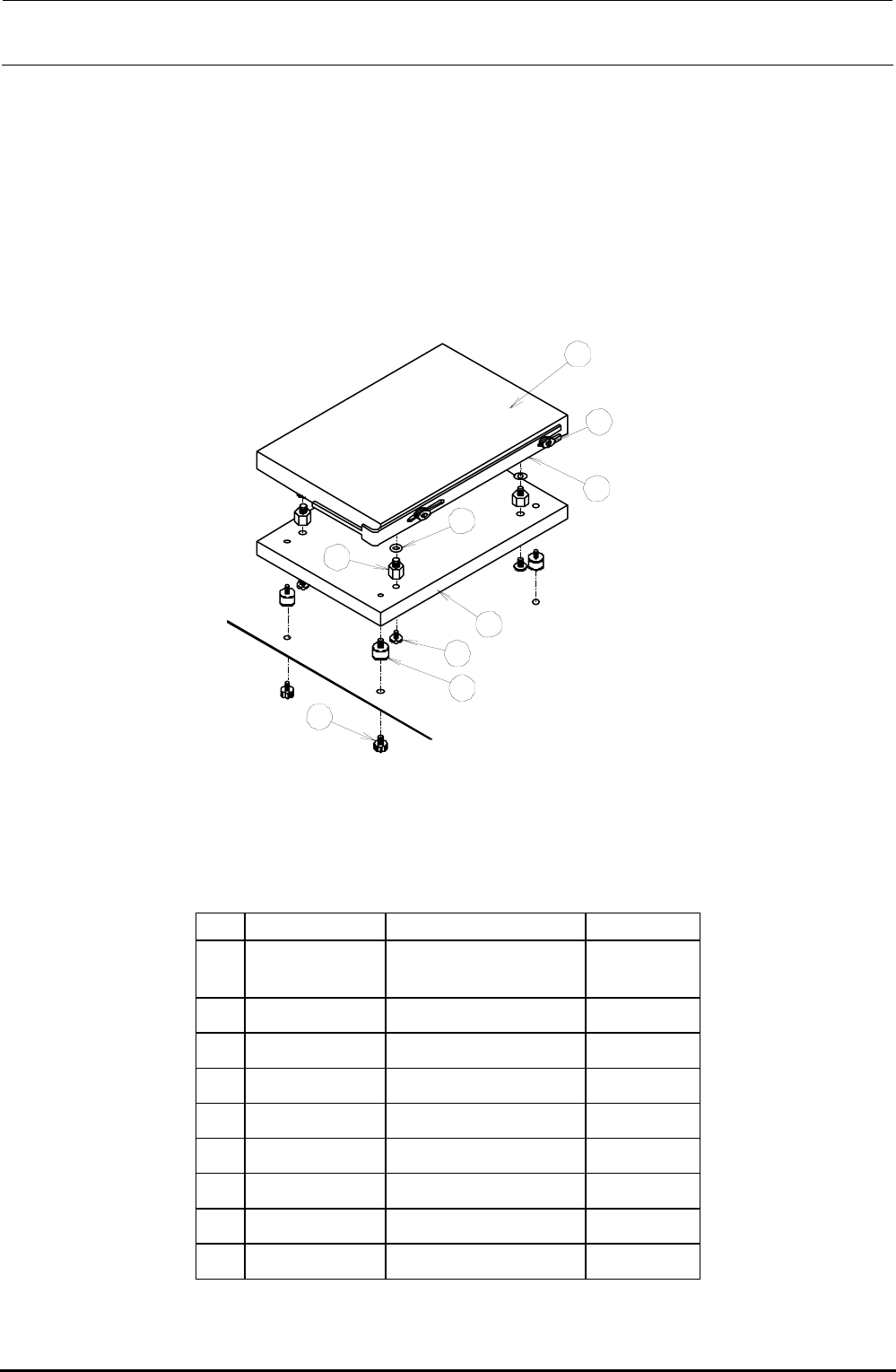
12-2-1-2. Replacing the SSD
The SSD is installed on the control support.
1) Remove the SEMS cap bolts to detach the overall SSD from the bracket while carefully
checking the IDE connector status.
2) Remove the SEMS cap bolts to detach the SSD bracket and disconnect the IDE
connector.
3) Remove the bolts and to detach the SSD from the weight plate .
4) Reassemble the components in the reverse order of disassembly.
Rev. 1.00
1
2
3
4
5
6
7
8
9
Figure 12-2-1-2-1 Replacement of SSD
[List of Replacement Parts]
Table 12-2-1-2-1 SSD Replacement Parts
No. Part No. Part name Q’ty/machine
40109193
ENVIRONMENT
SYSYTEM 132 ASM
1
40057003 SSD bracket 1
SL4030681SC
SEMS cap bolt (M3×6)
2
WP0320501SC Flat washer M3 4
E3032700000 Extension nipple 4
40011588 Weight plate 1
SL4030881SC
SEMS cap bolt (M3×8)
4
E1612721000 Vibration proof rubber 4
SL4030881SC
SEMS cap bolt (M3×8)
4
FX-3R Maintenance Guide
12-6
12-2-2. Setting Up the BIOS
After the SSD has been replaced, check the BIOS. If the settings are different from those described
in <Setting Method>, change the settings appropriately. In addition, if the CPU board is replaced, it
is absolutely necessary to change the BIOS.
Note: BIOS (Basic Input Output System)
The BIOS is an important program necessary to control the data input and output.
Therefore, always carefully operate the BIOS
. Normally, the programs are saved
into the flash memory on the CPU board and the setup data is saved into the SRAM
backed up by the battery.
Caution
12-2-2-1. Checking the Recognition of the SSD
You may check whether or not the BIOS recognizes the SSD correctly. If no automatic startable
SSD or FDD is found after memory check, the following message will appear.
Operating system not found
You can switch to the BIOS setting screen by pressing the <S> key. (Pressing the <R> key will
reset the unit.)
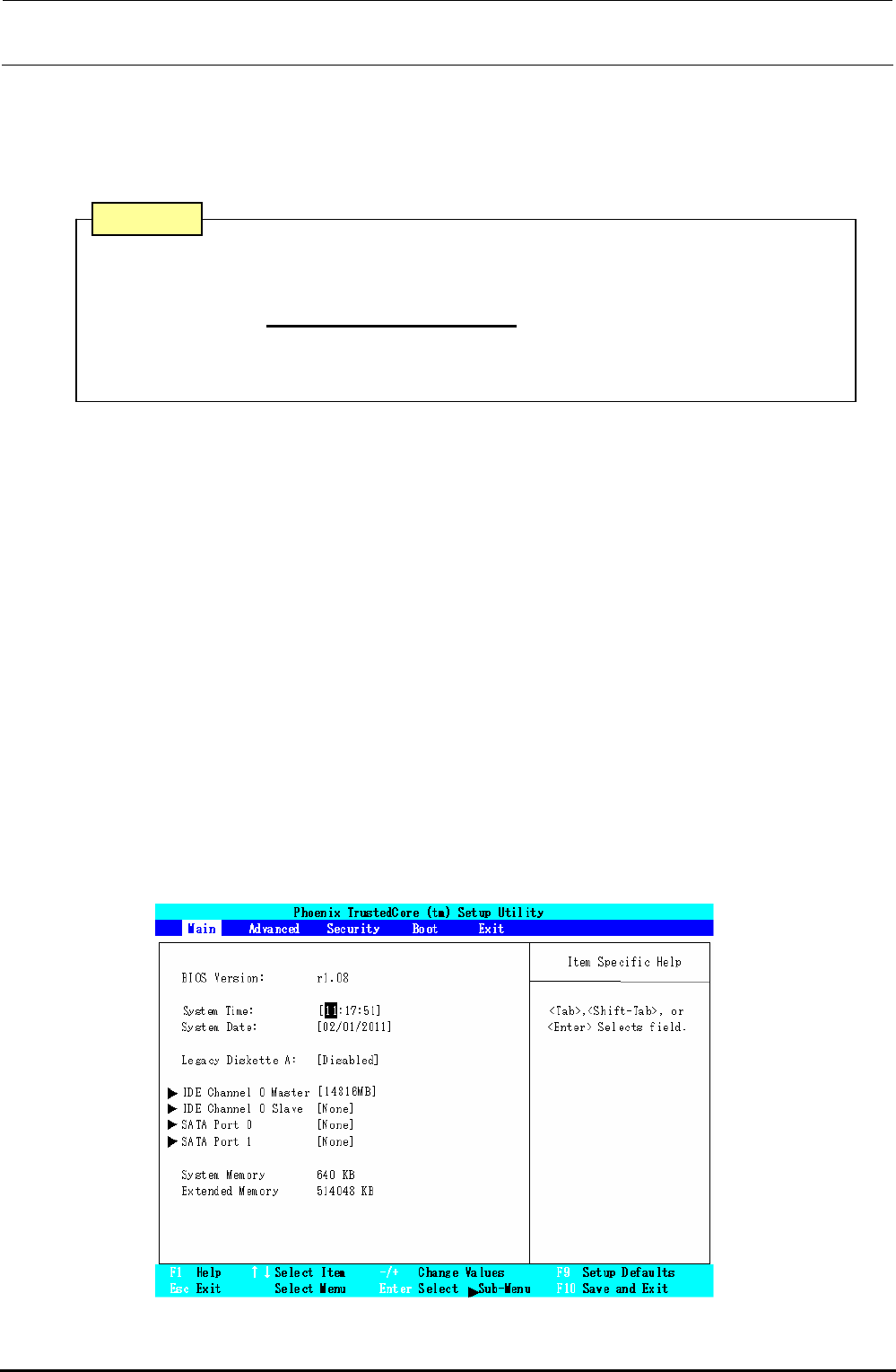
<Setting Method>
1) Display the BIOS screen.
Press the <F2> key while the “Phoenix Technologies” screen is displayed immediately
after the power has been turned ON.
After the operation step has moved to the BIOS setting, the following screen will appear.
Select a menu screen (Main, Advance, Security, Boot, Exit) with the [←] or [→] key, move
the cursor (highlighted portion) with the [↑] or [↓] key, and then press the <Enter> key to run
the item you have selected.
Figure 12-2-2-1-1 Screen Displayed after Moving to BIOS Setting
Rev. 1.00