JUKI FX-3R MAINTENANCE GUIDE.pdf - 第167页
FX-3R Maintenance Guide 12-38 (3) Replacement procedure 1) Replacing th e MPC and HUB The MPC and HUB are assembled into the HUB BOX mounted at the position shown below. First, disconnect the cables from the HUB-BOX. HUB…
FX-3R Maintenance Guide
12-37
12-3. HUB-BOX (RFID Applicable Option)
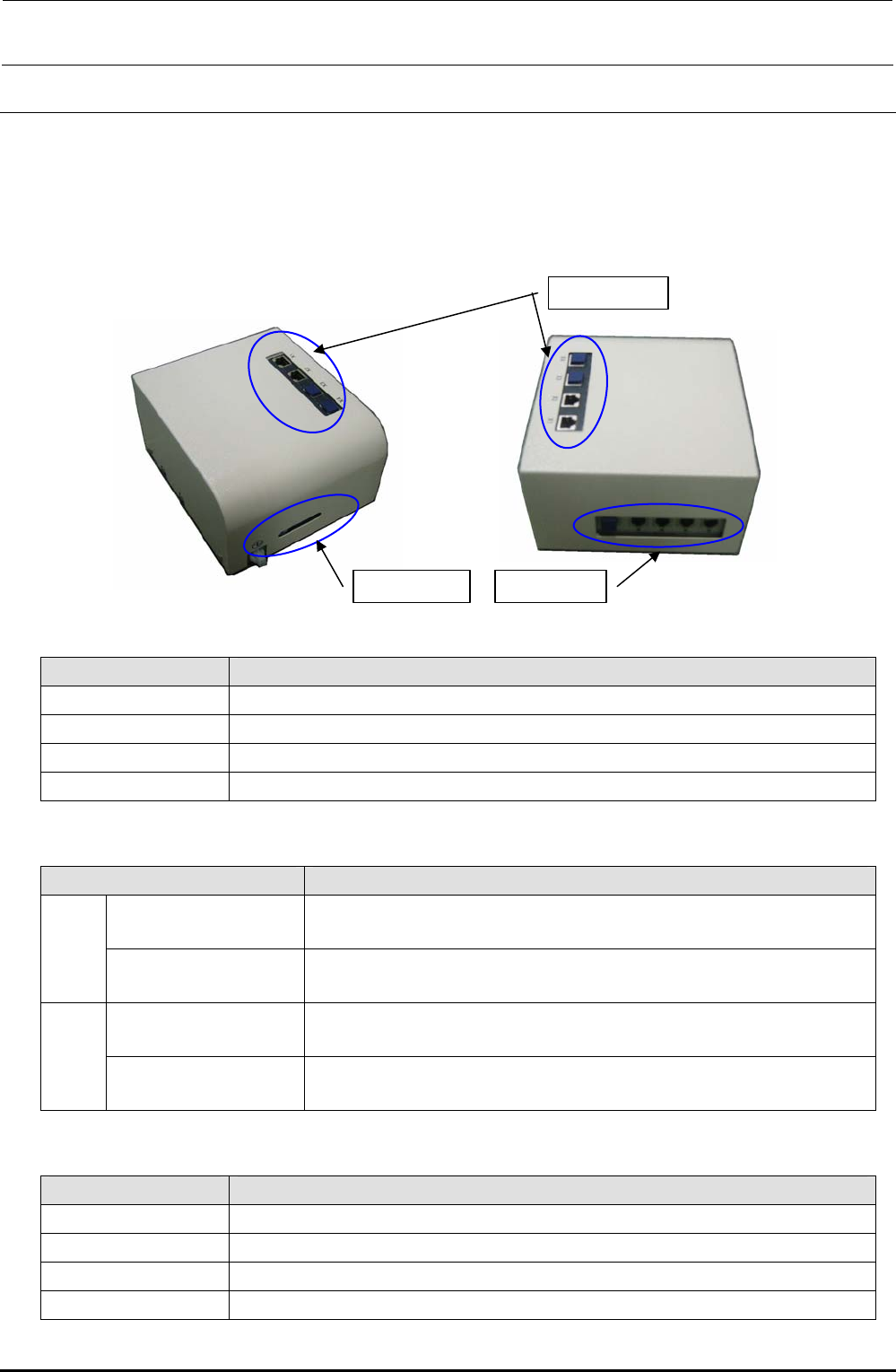
(1) Functions
This hub-box provides the switching hub function and the communication function with the
RFID antenna.
The RFID read results are transmitted to the CPU_BOARD through the HUB_BOX.
(2) Meaning of LED
Window 2
Window 1
Window 3
Window 1
Name Function
Power Shows that the power supply is connected to the controller.
Online Shows that the network connection with the server is established.
Link Shows that the electrical connection with the network is valid.
Activity Shows the data transmission between the controller and server.
Window 2
Name Function
LNK/ACT LNK: Lit
ACT: Flashes
X1
100 10 Mbps: Off
100 Mbps: Lit
LNK/ACT LNK: Lit
ACT: Flashes
X2
100 10 Mbps: Off
100 Mbps: Lit
Window 3
Name Function
Ch1 Establishment of communication with antenna (antenna array): Flashes.
Ch2 Same as above
Ch3 Same as above
Ch4 Same as above
Rev. 1.00
FX-3R Maintenance Guide
12-38
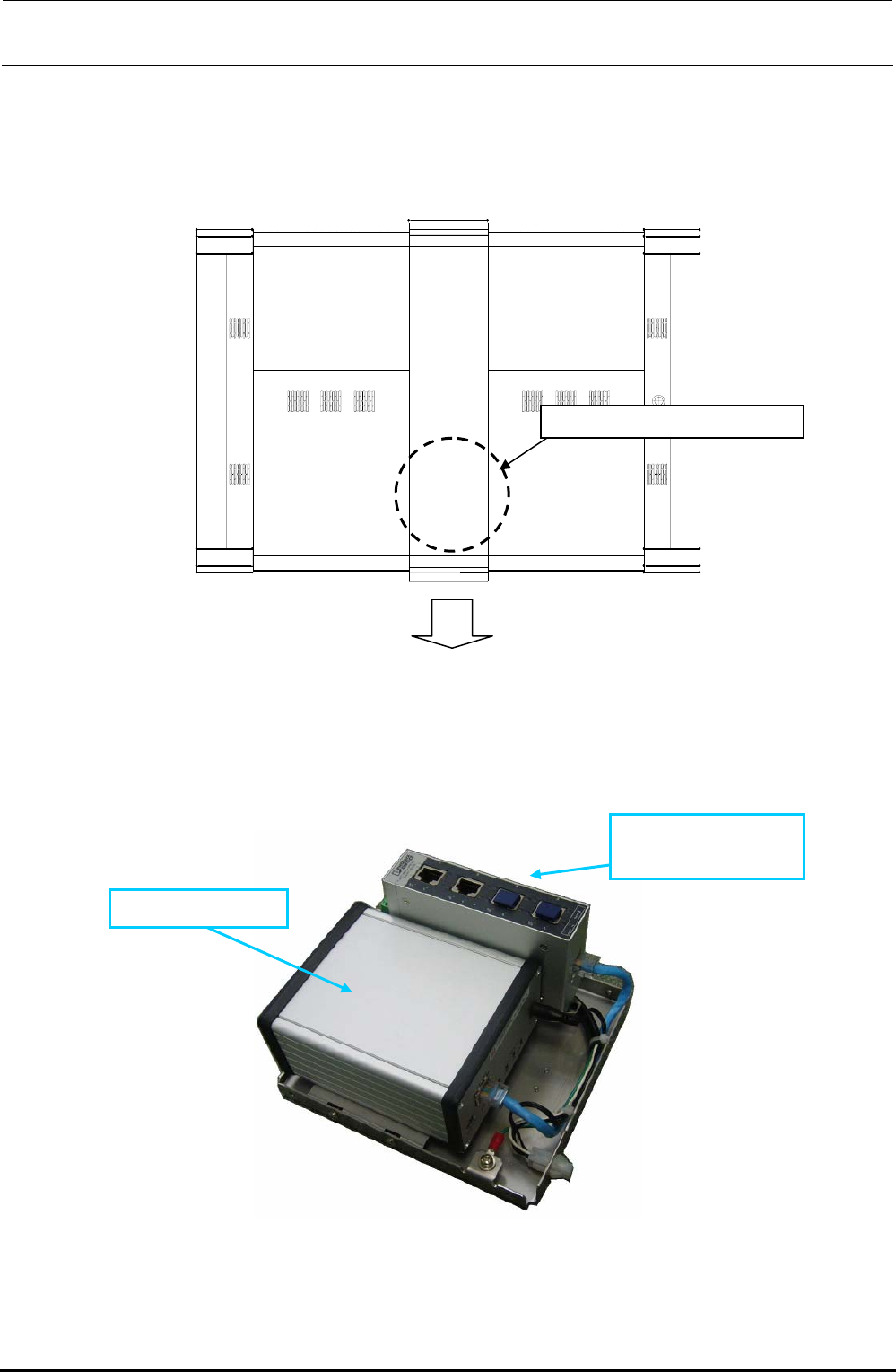
(3) Replacement procedure
1) Replacing the MPC and HUB
The MPC and HUB are assembled into the HUB BOX mounted at the position shown below.
First, disconnect the cables from the HUB-BOX.
HUB-BOX mountin
g
p
osition
Front of machine
Figure 12-3-1 Top View of Machine
Remove the cover set screws from the HUB BOX to detach the cover. You can see that the
MPC and SWITCHING HUB are assembled as follows.
40073032 MPC
40073033
SWITCHING HUB
Figure 12-3-2 HUB-BOX
Rev. 1.00
FX-3R Maintenance Guide
12-39
Rev. 1.00
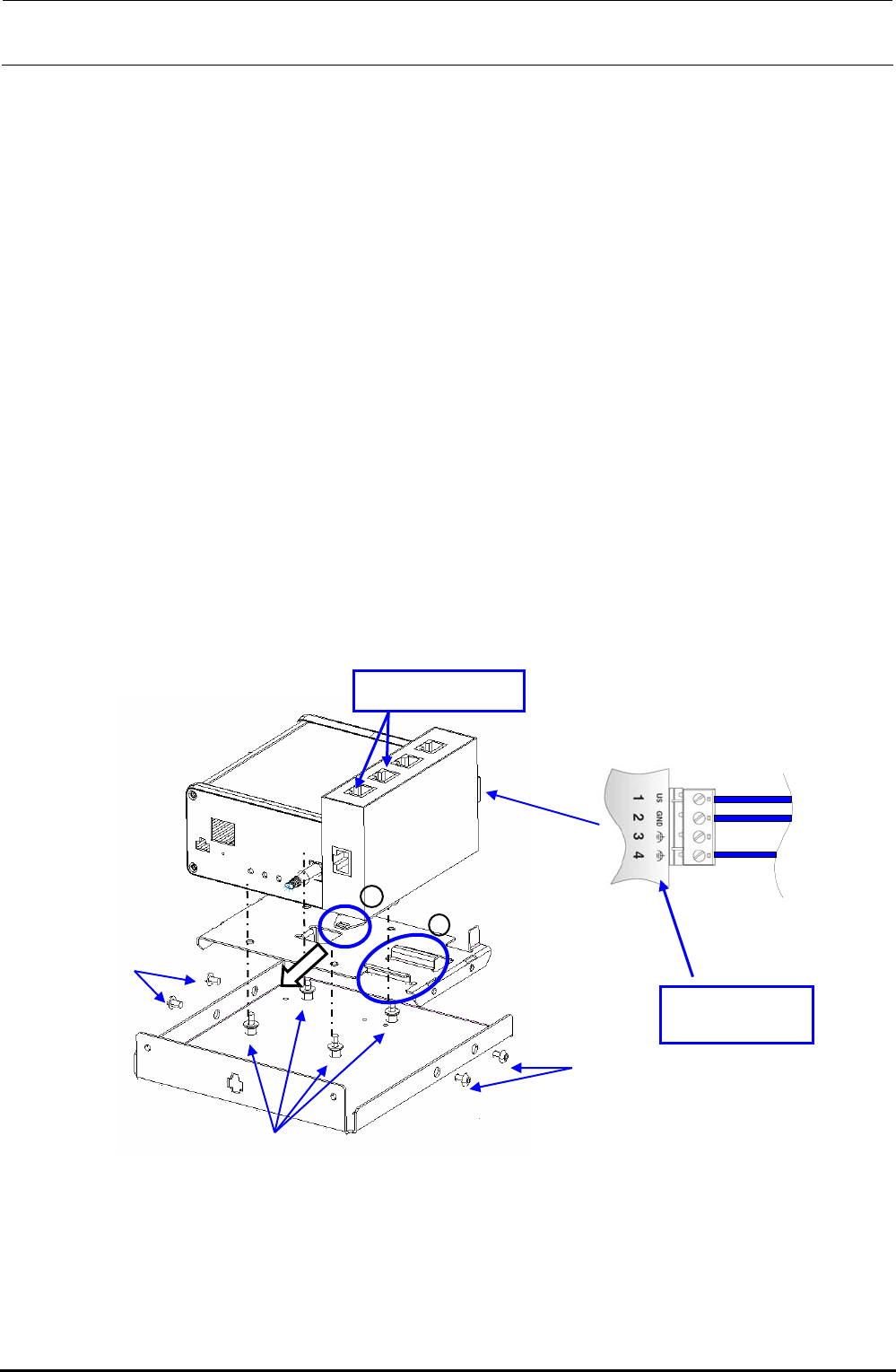
<Replacing the MPC>
c Disconnect the power connector and Ethernet cable from the MPC.
d Remove the fixing base set screws c.
e Remove the screws d securing the MPC to replace the MPC.
f After the MPC has been replaced, reassemble the components in the reverse order of
disassembly.
At this time, remove the dust-proof cover from the MPC Prog terminal before replacement
and mount it on a new MPC that has been changed.
g Follow the steps stated in “Appendix A, Setup Instructions” of “Instruction Manual for Intelli
SCS” to register the MPC.
<Replacing the SWITCHING HUB>
c Disconnect the Ethernet cable from the HUB and the power cable from the power terminal
block.
d Pull the part A in the direction indicated by an arrow to detach it from the part B shown in the
Figure.
e After the SWITCHING HUB has been replaced, reassemble the components at their original
positions in the reverse order of disassembly.
f Detach the dust-proof cover that protects the blank port of the HUB before replacement and
mount it on a new HUB after completion of the replacement.
Figure 12-3-2 Replacement of Components inside HUB-BOX
A
B
c
c
d
Power terminal
block
Dust proof cover