JUKI FX-3R MAINTENANCE GUIDE.pdf - 第169页
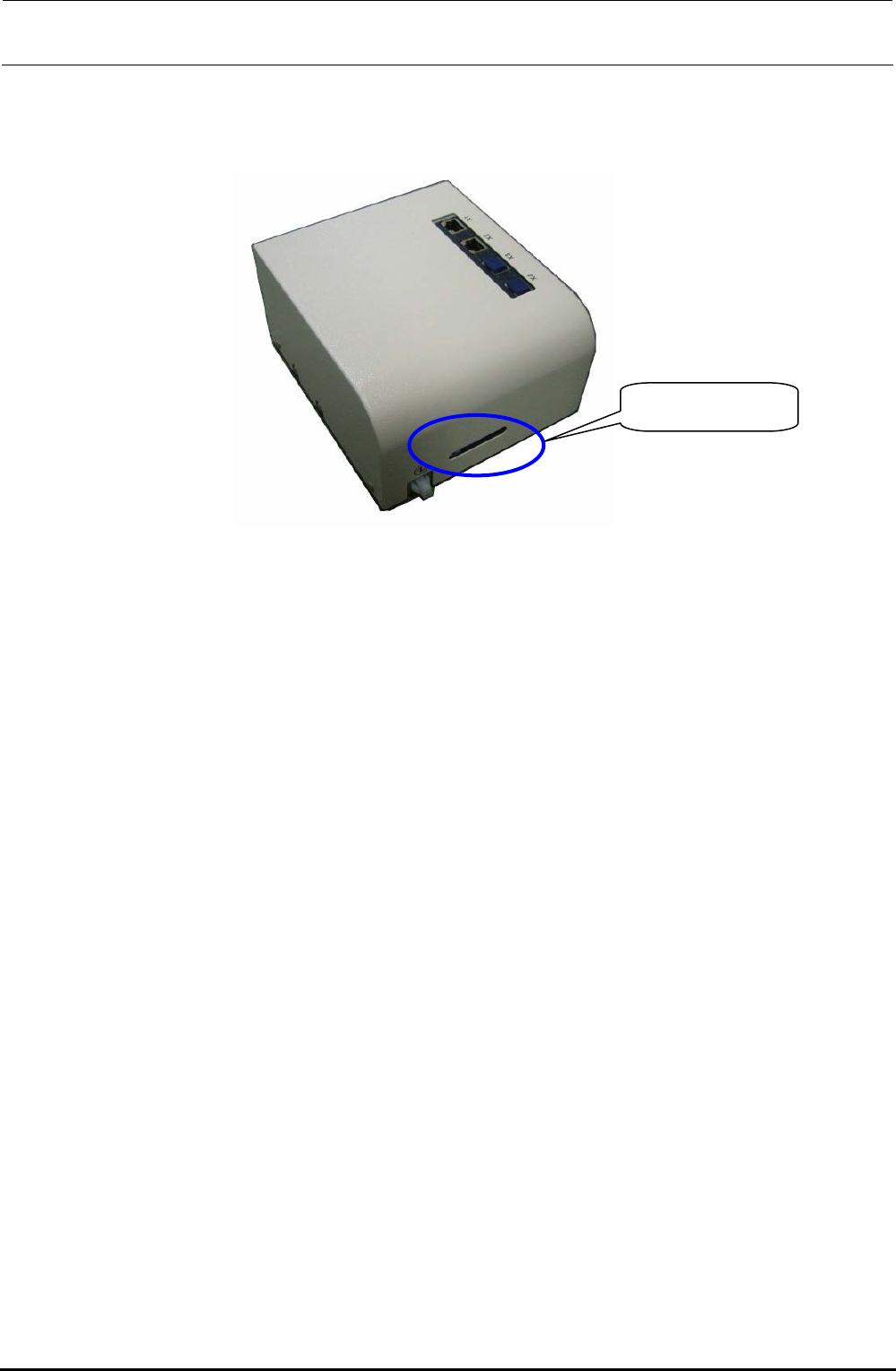
FX-3R Maintenance Guide 12-40 When mounting the cover again, assemble the cable as shown in the Figure so that it does not block the cover window. Make sure that the LED lamps can be seen through the window. Cover window…
FX-3R Maintenance Guide
12-39
Rev. 1.00
<Replacing the MPC>
c Disconnect the power connector and Ethernet cable from the MPC.
d Remove the fixing base set screws c.
e Remove the screws d securing the MPC to replace the MPC.
f After the MPC has been replaced, reassemble the components in the reverse order of
disassembly.
At this time, remove the dust-proof cover from the MPC Prog terminal before replacement
and mount it on a new MPC that has been changed.
g Follow the steps stated in “Appendix A, Setup Instructions” of “Instruction Manual for Intelli
SCS” to register the MPC.
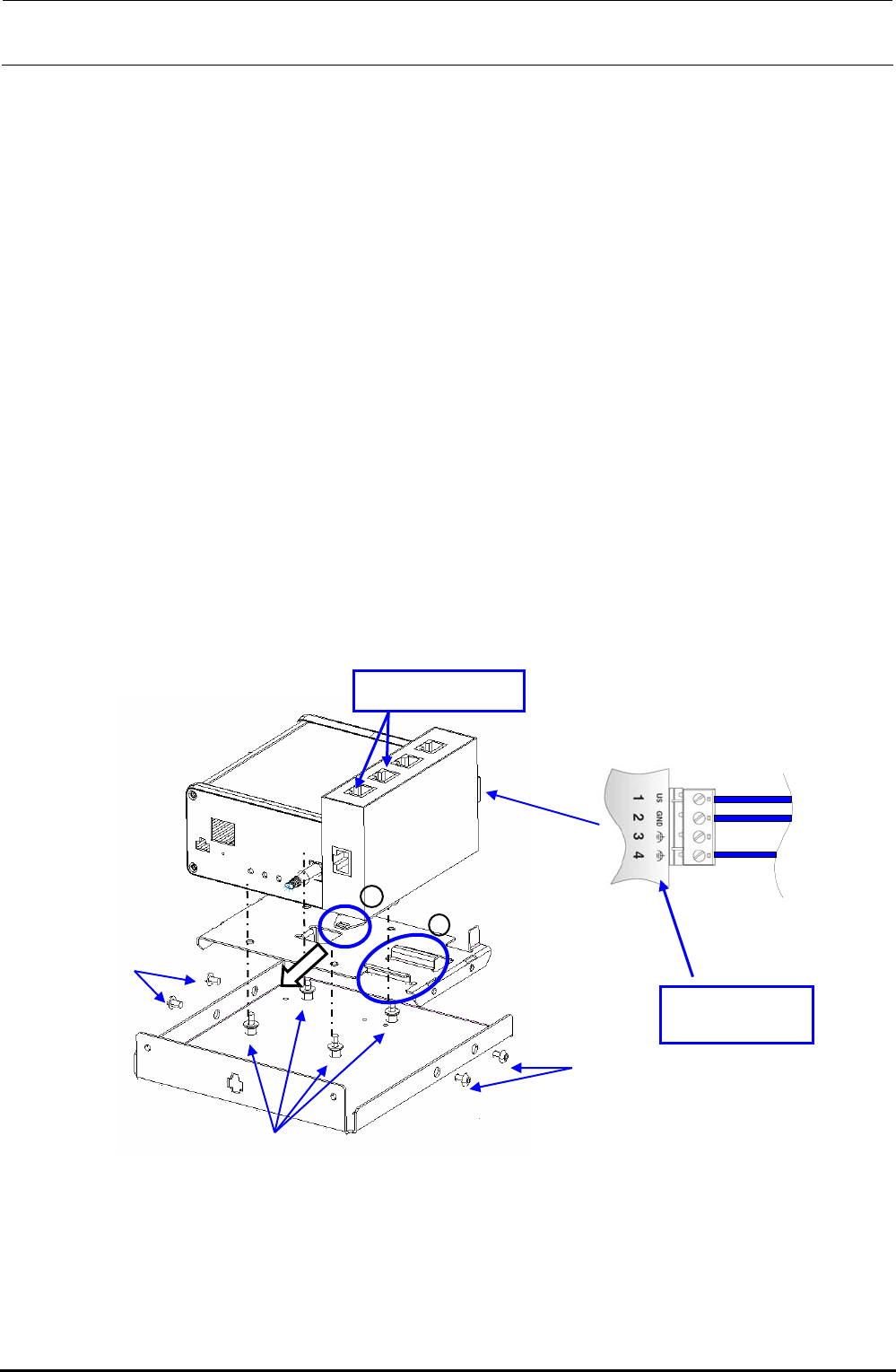
<Replacing the SWITCHING HUB>
c Disconnect the Ethernet cable from the HUB and the power cable from the power terminal
block.
d Pull the part A in the direction indicated by an arrow to detach it from the part B shown in the
Figure.
e After the SWITCHING HUB has been replaced, reassemble the components at their original
positions in the reverse order of disassembly.
f Detach the dust-proof cover that protects the blank port of the HUB before replacement and
mount it on a new HUB after completion of the replacement.
Figure 12-3-2 Replacement of Components inside HUB-BOX
A
B
c
c
d
Power terminal
block
Dust proof cover
FX-3R Maintenance Guide
12-40
When mounting the cover again, assemble the cable as shown in the Figure so that it does not block
the cover window. Make sure that the LED lamps can be seen through the window.
Cover window
Figure 12-3-3 Cover Window
Rev. 1.00
FX-3R Maintenance Guide
13-1
DANGER
To prevent any trouble caused by accidental machine start, always
shut-down the power before starting the maintenance and
adjustment work.
[13] ELECTRICAL COMPONENTS
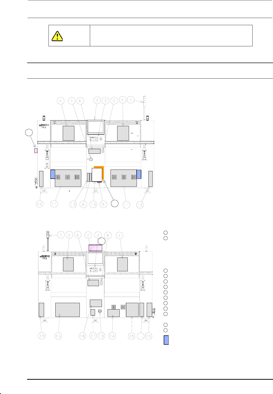
13-1. Layout of Electrical Components
Figure 13-1-1 shows the front view and Figure 13-1-2 shows the rear view.
c Signal tower
d LCD monitor
e Operation panel
Front: Operation board front assembly
Rear: Operation board rear assembly
(EN assembly for machines with EN
specifications)
f Head unit
21
Head main board assembly, Z/θ-servo
amplifier, HMS, OCC camera, OCC light
board
(OCC-A board assembly, OCC-C board
assembly),
Bad mark reader (Optional)
g Mouse
h Keyboard
i Power switch
j FDD
k SSD
l Control unit
Inside: CPU board, POSITION board,
IEEE1394A board, IP-X5 board,
CPCI back board
20
Figure 13-1-1 Front View
Outside: Superimpose board,
Mouse/keyboard change-over
board
11
XY-driver unit
12
Transport unit system electrical
components
5-phase stepping drivers (For transport
motor, auto PWB width adjustment, and
backup table), Base carry board assembly
(One board on right side only.)
22
13
DVD-ROM & CD-R/RW drive
14
Vacuum pump
15
Power supply unit
16
AC input unit L, AC input unit R
17
Circuit breaker
18
Hour meter
19
Feeder board assembly
20
ATX power supply
21
Barcode reader (Optional)
∗ To be installed on the transport IN side.
22
HUB-BOX (Optional)
23
XY-RELAY board assembly
23
portion Tester for CVS
Figure 13-1-2 Rear View
Rev. 1.00