JUKI FX-3R MAINTENANCE GUIDE.pdf - 第17页
FX-3R Maintenance Guide 1-9 1-3-2. Replacing the Y-Axis Cable Bear (1) Remove the screws and hexagon nuts fixing the Y-cable bear. (2) Open the flap of the Y-cable bear, disconnect the cables, and replace the cable bear.…
FX-3R Maintenance Guide
1-8
1-3. Replacing the Cable Bear
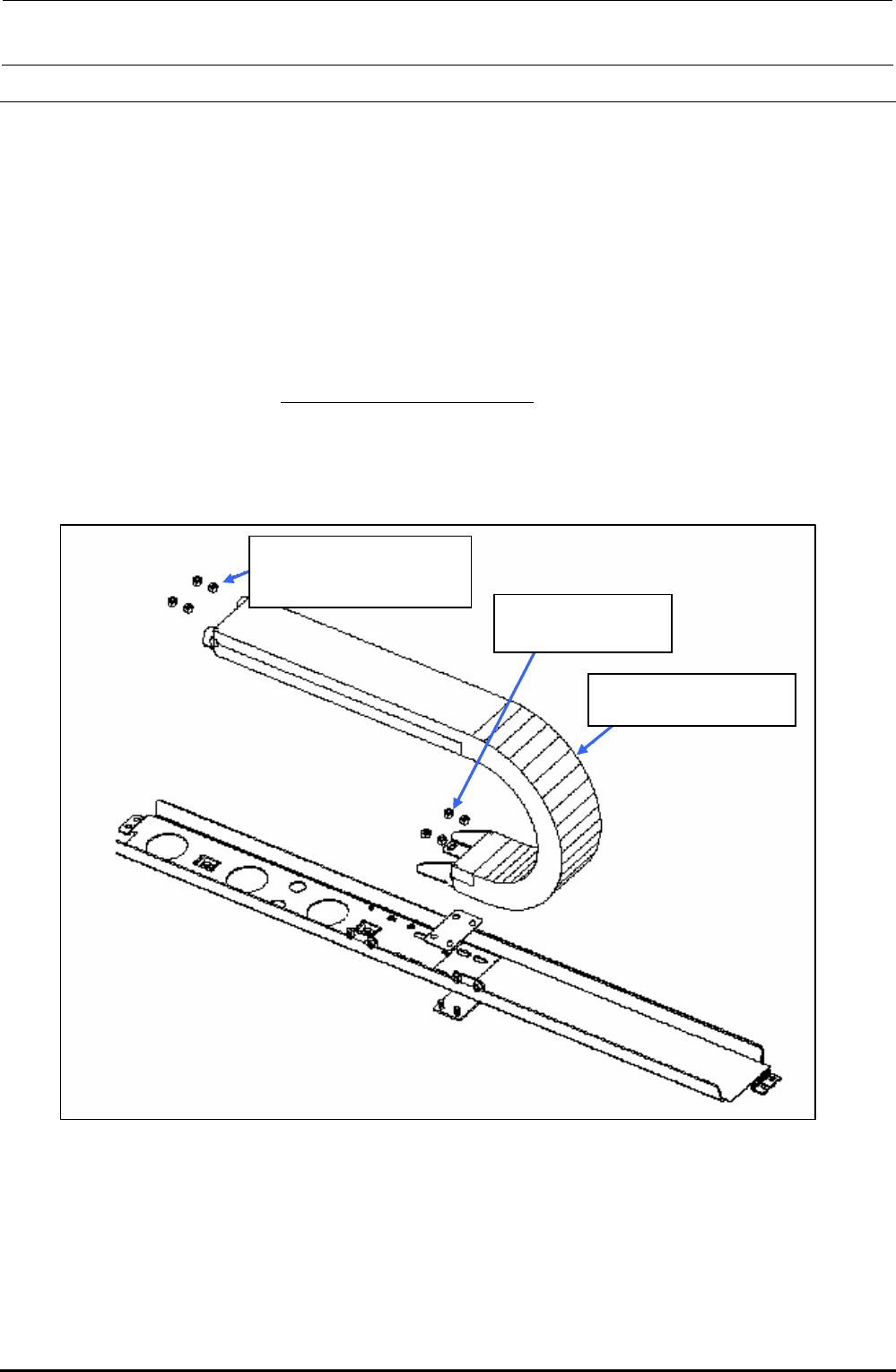
1-3-1. Replacing the X-Axis Cable Bear
(1) Remove the screws and hexagon nuts fixing the X-cable bear.
(2) Open the flap of the X-cable bear, disconnect the cables, and replace the cable bear.
(3) Apply the grease evenly to four surfaces inside the cable bear.
(The reference applying amount is that whitish grease can be checked.)
(4) Reassemble the parts and components in the reverse order of disassembly. At this time, pay
special attention so that
any cables are not entangled inside the cable bear.
∗ After the grease has been applied, check the cables in the cable bear. When necessary, apply
the grease again.
GERALYN grease (MGREAS400GA)
SL3061232TN
Washer assembled
round screw, M6 × 12
NM6060001SC
Hexagon nut M6
40046786
X-cable bear
Figure 1-3-1-1 X-Axis Cable Bear
Rev. 1.00
FX-3R Maintenance Guide
1-9
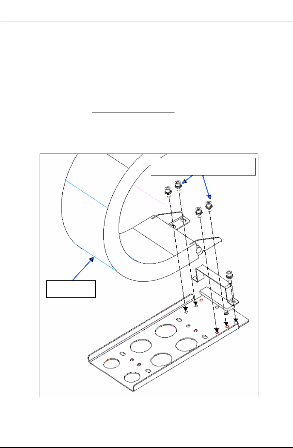
1-3-2. Replacing the Y-Axis Cable Bear
(1) Remove the screws and hexagon nuts fixing the Y-cable bear.
(2) Open the flap of the Y-cable bear, disconnect the cables, and replace the cable bear.
(3) Apply the grease evenly to four surfaces inside the cable bear.
(The reference applying amount is that whitish grease can be checked.)
(4) Reassemble the parts and components in the reverse order of disassembly. At this time, pay
special attention so that
any cables are not entangled inside the cable bear.
∗ After the grease has been applied, check the cables in the cable bear. When necessary, apply
the grease again.
GERALYN grease (MGREAS400GA)
40046709
Y-cable bear
SL6061292TN
SEMS cap bolt with washer M6 × 12
Figure 1-3-2-1 Y-Axis Cable Bear
Rev. 1.00
FX-3R Maintenance Guide
1-10
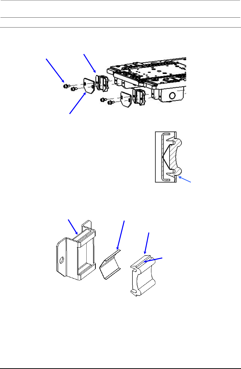
1-4. Replacing the Roller Lubrication Part
(1) Remove the screws that secure the lubrication unit.
(2) Insert a precision screwdriver (−) into the portion
indicated by an arrow shown in the Fig. on the right
to detach the lubrication part from the bracket.
Lubrication unit
Fixing screw
Scraper
(3) Prepare a new lubrication part. Fit the spring part to the lubrication part and assemble it into the
bracket.
Lubrication part (replacement part)
Spring part (replacement part)
Bracket
Surface A
(4) To assemble the lubrication part, make the surface shown in the Fig. on the right in step (2) and
press-fit the lubrication part while applying the force to the surface A.
(5) Assemble the lubrication unit and scraper into the roller using the fixing screws.
Adjust the position so that the clearance between the scraper part and roller traveling surface is
0.1 to 0.2 mm, and then tighten the screws firmly.
Rev. 1.00