JUKI FX-3R MAINTENANCE GUIDE.pdf - 第171页
FX-3R Maintenance Guide 13-2 13-2. La y o ut of Top of Base Frame Figure 13-2-1 shows the base frame top view. Rev . 1.00 h e d 13 i c l d 11 15 c LCD monito r d Head unit e Transformer f YL-LF-axis motor g YR-LF-axis mo…
FX-3R Maintenance Guide
13-1
DANGER
To prevent any trouble caused by accidental machine start, always
shut-down the power before starting the maintenance and
adjustment work.
[13] ELECTRICAL COMPONENTS
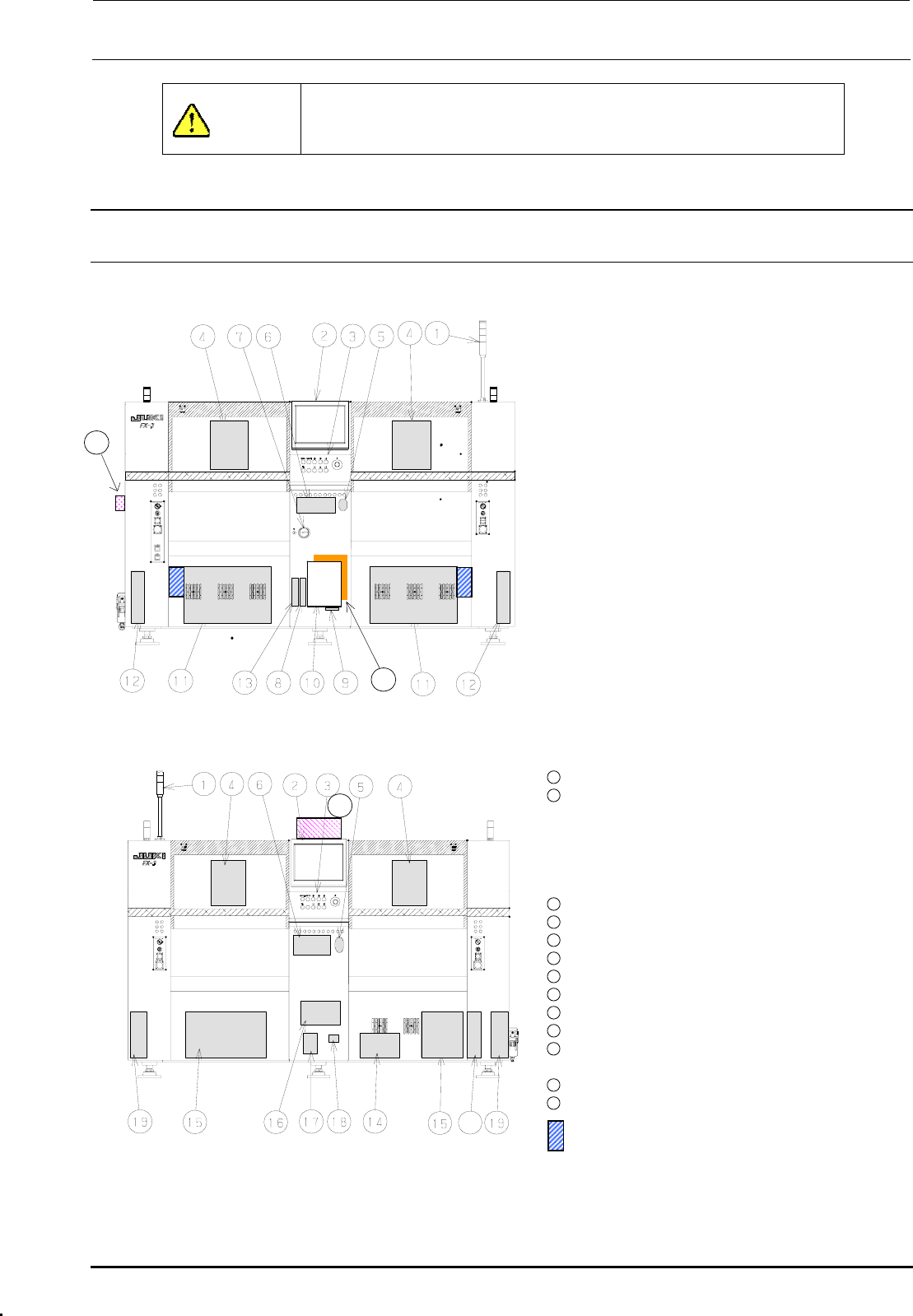
13-1. Layout of Electrical Components
Figure 13-1-1 shows the front view and Figure 13-1-2 shows the rear view.
c Signal tower
d LCD monitor
e Operation panel
Front: Operation board front assembly
Rear: Operation board rear assembly
(EN assembly for machines with EN
specifications)
f Head unit
21
Head main board assembly, Z/θ-servo
amplifier, HMS, OCC camera, OCC light
board
(OCC-A board assembly, OCC-C board
assembly),
Bad mark reader (Optional)
g Mouse
h Keyboard
i Power switch
j FDD
k SSD
l Control unit
Inside: CPU board, POSITION board,
IEEE1394A board, IP-X5 board,
CPCI back board
20
Figure 13-1-1 Front View
Outside: Superimpose board,
Mouse/keyboard change-over
board
11
XY-driver unit
12
Transport unit system electrical
components
5-phase stepping drivers (For transport
motor, auto PWB width adjustment, and
backup table), Base carry board assembly
(One board on right side only.)
22
13
DVD-ROM & CD-R/RW drive
14
Vacuum pump
15
Power supply unit
16
AC input unit L, AC input unit R
17
Circuit breaker
18
Hour meter
19
Feeder board assembly
20
ATX power supply
21
Barcode reader (Optional)
∗ To be installed on the transport IN side.
22
HUB-BOX (Optional)
23
XY-RELAY board assembly
23
portion Tester for CVS
Figure 13-1-2 Rear View
Rev. 1.00
FX-3R Maintenance Guide
13-2
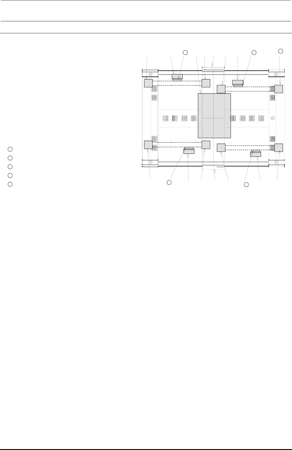
13-2. Layout of Top of Base Frame
Figure 13-2-1 shows the base frame top view.
Rev. 1.00
h
ed 13 i c l d
11
15
c LCD monitor
d Head unit
e Transformer
f YL-LF-axis motor
g YR-LF-axis motor
h YL-LR-axis motor
i YR-LR-axis motor
j YL-RF-axis motor
k YR-RF-axis motor
l YL-RR-axis motor
11
YR-RR-axis motor
12
X-LF-axis motor
13
X-LR-axis motor
14
X-RF-axis motor
f
12
d
g
c
j
15
X-RR-axis motor
14
d
k
Figure 13-2-1 Base Frame Top View
FX-3R Maintenance Guide
13-3
Rev. 1.00
13-3. Power Supply Unit
13-3-1. Structure of Power Supply Unit
Two power supply units are mounted on the left and right at the rear of the machine. Figure
13-3-1-2-1 and Figure 13-3-1-2-2 show the structure drawings of the power supply unit.
The power supply unit is composed of DC power supplies, control relays, and circuit protectors, and
designed to supply the AC and DC power to the units (control unit, X-Y unit, Z-θ unit, transport
unit, and head unit.)
The following shows the application of each DC power supply.
• +6V (+6.3V to 6.5V, PS1): For controlling of feeder (stacking, 32mm-paper tape)
• +24VA (+24±0.1V, PS2): General-purpose (For control unit outer board, stepping driver, etc.)
• +24VB (+24±0.1V, PS3): For control of Zθ-servo amplifier
• +24VC (+24±0.1V, PS4): For driving of safety circuit (EN machine only)
• +24VC (+26±0.1V, PS5): For EFT power supply
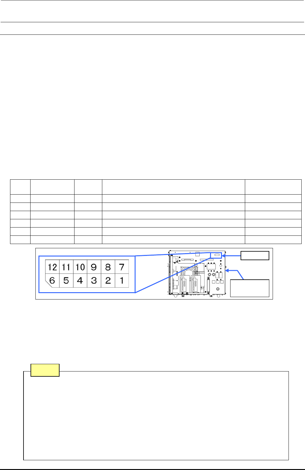
13-3-1-1. Adjusting Method of DC Power Source Voltage Level
Table 13-3-1-1-1 DC Power Source Voltage Level Settings
No.
Power
specifications
Power
symbol
Measurement terminals of power supply unit
Voltage adjustment
value
1 (∗) +48V - CN 039 Pin No. 1 (+48V) and Pin No. 7 (+48VRTN) -
2 +6V PS 1 CN 039 Pin No. 3 (+6V) and Pin No. 9 (+6VRTN) (+6.3 to 6.5V)
3 +24V PS 2 CN 039 Pin No. 4 (+24VA) and Pin No. 10 (+24VARTN) (+24V±0.1V)
4 +24V PS 3 CN 039 Pin No. 5 (+24VB) and Pin No. 11 (+24VBRTN) (+24V±0.1V)
5 +24V PS 4 CN 039 Pin No. 6 (+24VC) and Pin No. 12 (+24VCRTN) (+24V±0.1V)
6 +24V PS 5 CN 039 Pin No. 2 (+26V) and Pin No. 8 (+24VRTN) (+26V±0.1V)
Figure 13-3-1-1-1 Power Supply Unit CN039
• The DC power output voltage is to be adjusted on the CN039 (connector on the front of the
power supply unit) of the power supply unit.
• No. 1 with an asterisk (∗) is a power supply line not needing any adjustment.
• Pull out the PSU BRACKETs (PS1, PS3, PS4) or adjust the output voltage potentiometer of each
power supply of the PS2 and PS5 located on the front of the DC power supply so that the DC
power output voltage levels No. 2 to 6 are specified adjustment values.
CN039
Power
supply unit
Note 1. Carefully adjust the variable resistor so that the voltage value does not
exceed the specified adjustment level.
Note 2. Never connect CN039-7 and 8 pins to the GND line of a power supply
unit other than that to be adjusted.
Note 3. PS4 is a DC power supply for the EN specifications mounted on the
POWER UNIT (EN) and is not mounted on the POWER UNIT.
Note 4. Before adjusting the voltage of the PS5, disconnect the connectors of the
electric bank. (Adjust the voltage in the no-load status.)
Note