JUKI FX-3R MAINTENANCE GUIDE.pdf - 第182页
FX-3R Maintenance Guide 13-13 Figure 13-3-1-3-7 Connec tion Diagram for the Z/ θ Power Supply Board Rev . 1.00
FX-3R Maintenance Guide
13-12
(
1
-
5
B
)
C
N
0
8
1
C
P
1
1
(
1
0
A
)
H
A
0
0
5
4
2
0
0
0
C
O
U
T
I
N
t
o
E
L
E
C
B
A
N
K
I
/
F
F
R
O
N
T
C
N
0
6
9
C
N
0
7
0
C
P
1
2
(
2
5
A
)
H
A
0
0
5
2
7
0
0
0
C
I
N
O
U
T
P
4
0
1
P
4
0
2
t
o
P
O
W
E
R
M
O
N
I
T
O
R
C
N
0
6
7
P
4
0
7
H
X
0
0
6
7
5
0
0
0
0
t
o
E
L
E
C
B
A
N
K
I
/
F
R
E
A
R
t
o
F
E
E
D
E
R
P
C
B
P
4
0
9
A
C
1
0
0
V
I
N
P
U
T
T
F
-
1
0
0
L
T
F
-
1
0
0
N
F
G
P
4
0
3
P
4
0
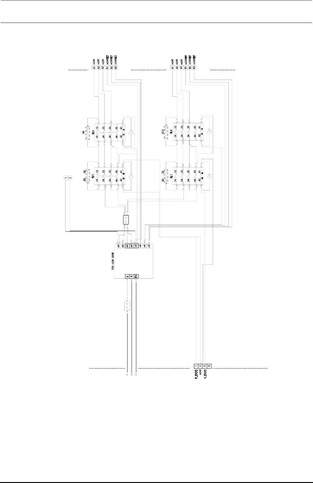
5
Figure 13-3-1-3-6 Connection Diagram for the Power Supply Unit (EN) (3/3)
Rev. 1.00

FX-3R Maintenance Guide
13-13
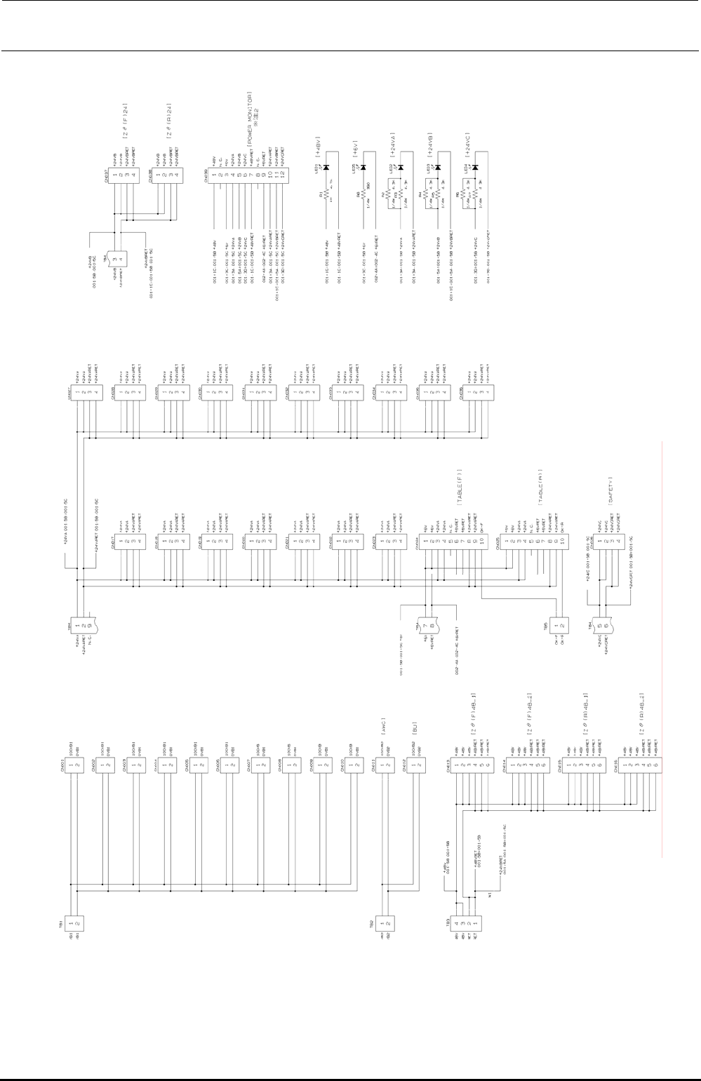
Figure 13-3-1-3-7 Connection Diagram for the Z/θ Power Supply Board
Rev. 1.00
FX-3R Maintenance Guide
13-14
∗ Note 1: Indicate the bracketed inscriptions by silk-screen printing.
∗ Note 2: Indicate the signal names of CN039 by silk-screen printing (excluding N. C.).
∗ Note 3: Connect the OK signals of CN024 and 025 so that +24VARET patterns sandwich them.
∗ Note 3
∗ Note 3
Figure 13-3-1-3-8 Connection Diagram for the Power Supply Board
Rev. 1.00