JUKI FX-3R MAINTENANCE GUIDE.pdf - 第198页
FX-3R Maintenance Guide 13-29 [Replacement procedure] c Before starting the replacement work, always turn OFF the main power, main circuit breaker, and main switch. d The battery unit is located on the left in front of t…
FX-3R Maintenance Guide
13-28
13-4-10. Battery Unit (40048007)
WARNING
To avoid serious personal injury caused by electric shock, always
turn OFF the main switch completely.
Make sure that the main circuit breaker and main switch of the
main unit are turned OFF.
The main switch is a power switch mounted inside the building and
does not mean a switch on the machine main unit.
WARNING
(1) Before starting the work, take off a watch, ring, necklace, or
other metallic object.
(2) Always use tools with insulated grip.
(3) Do not put any tool or metallic part on the battery.
Rev. 1.00
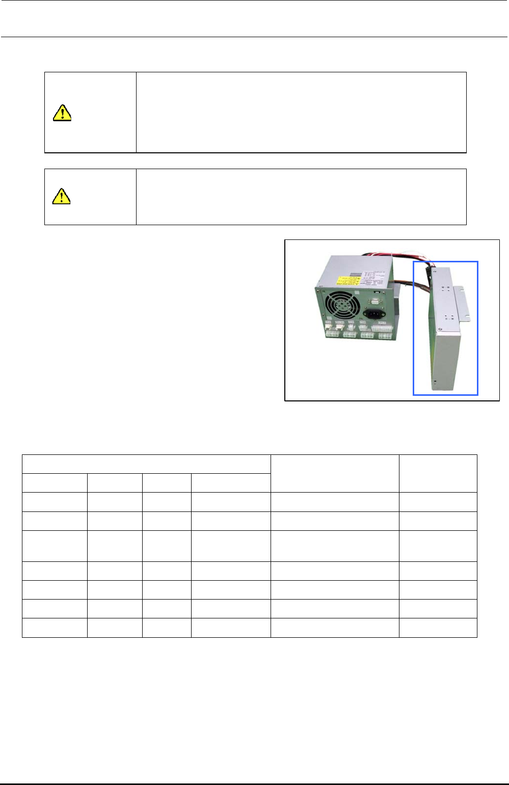
[Functions]
If a power failure occurs, the control box is
backed up by this battery unit through the
connected ATX power supply (40048006).
[DIP switch settings]
There are no DIP switches on the battery unit.
[Meaning of LED]
The following shows the status of the LED for
indication of the battery unit.
Figure 13-4-10-1 Battery Unit
Table 13-4-10-1 LED Status Indications
Power supply status
AC input DC output Charger Battery
LED status Remarks
Normal Stop Stop
−
Off Standby
Normal Normal Normal Charging Orange (Lit) Power ON
Normal Normal Stop Fully charged
(80% or more)
Green (Lit) Power ON
Power failure Normal Stop Normal (Backup) Orange (Flashing) Backup
Normal Normal Error Normal Green/orange (Lit alternately) Charger failure
Normal Normal Normal Error Green/orange (Lit alternately)
Battery error
∗
1
Normal
Stop
∗
2
Normal Normal Green/orange (Lit alternately) DC output error
∗1. The battery charging may be stopped if the temperature of the battery built-into the unit is
45°C or more.
∗2. DC+5VSB output is excluded.
[Adjustment items after replacement]
There are no particular adjustment items.
[Replacement timing]
The battery is replaced at reference intervals of three years.
FX-3R Maintenance Guide
13-29
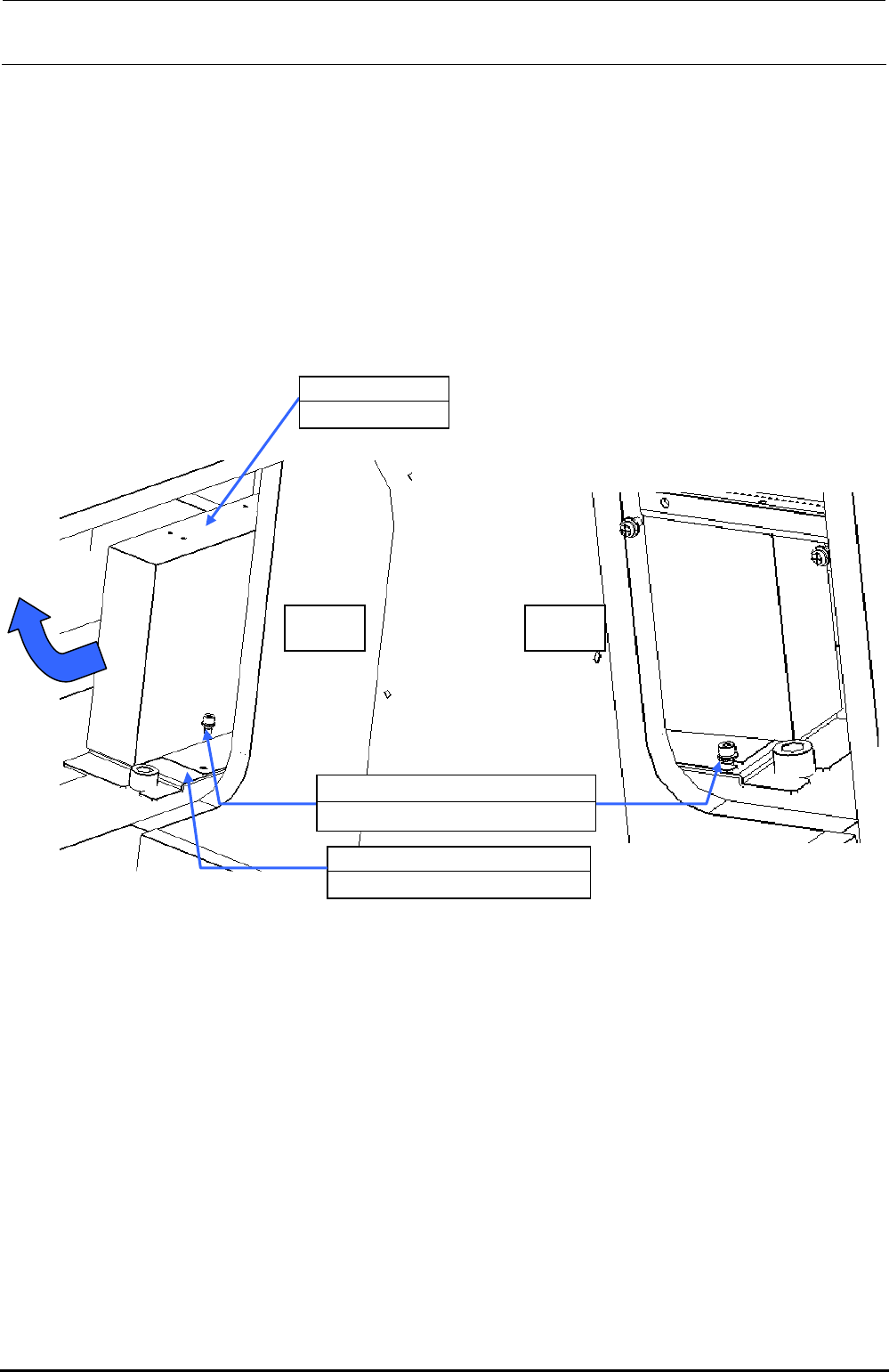
[Replacement procedure]
c Before starting the replacement work, always turn OFF the main power, main circuit
breaker, and main switch.
d The battery unit is located on the left in front of the base frame center and below the ATX
power supply (40048006). Remove SL6041092TN (1 pc.) on the left and loosen
SL6040892TN (1 pc.) on the right to detach the battery unit together with the BATTERY
SUPPORT PLATE (40092122).
e Remove four inch screws (40048047) to detach the battery unit from the BATTERY
SUPPORT PLATE (40092122).
Additionally, disconnect the cables from the ATX power supply.
f Replace the battery unit with a new one. Reassemble the parts and components in the
reverse order of disassembly.
Left Right
40048007
Battery unit
40092122
BATTERY SUPPORT PLATE
SL6040892TN
×
2
SEMS cap bolt with washer M4×8
Figure 13-4-10-2 Detaching the Battery Unit
Rev. 1.00
FX-3R Maintenance Guide
13-30
13-5. X-Y Unit
The X-Y unit is composed of AC servo amplifier that drives the X/Y-axes and a magnescale that
detects the movement position.
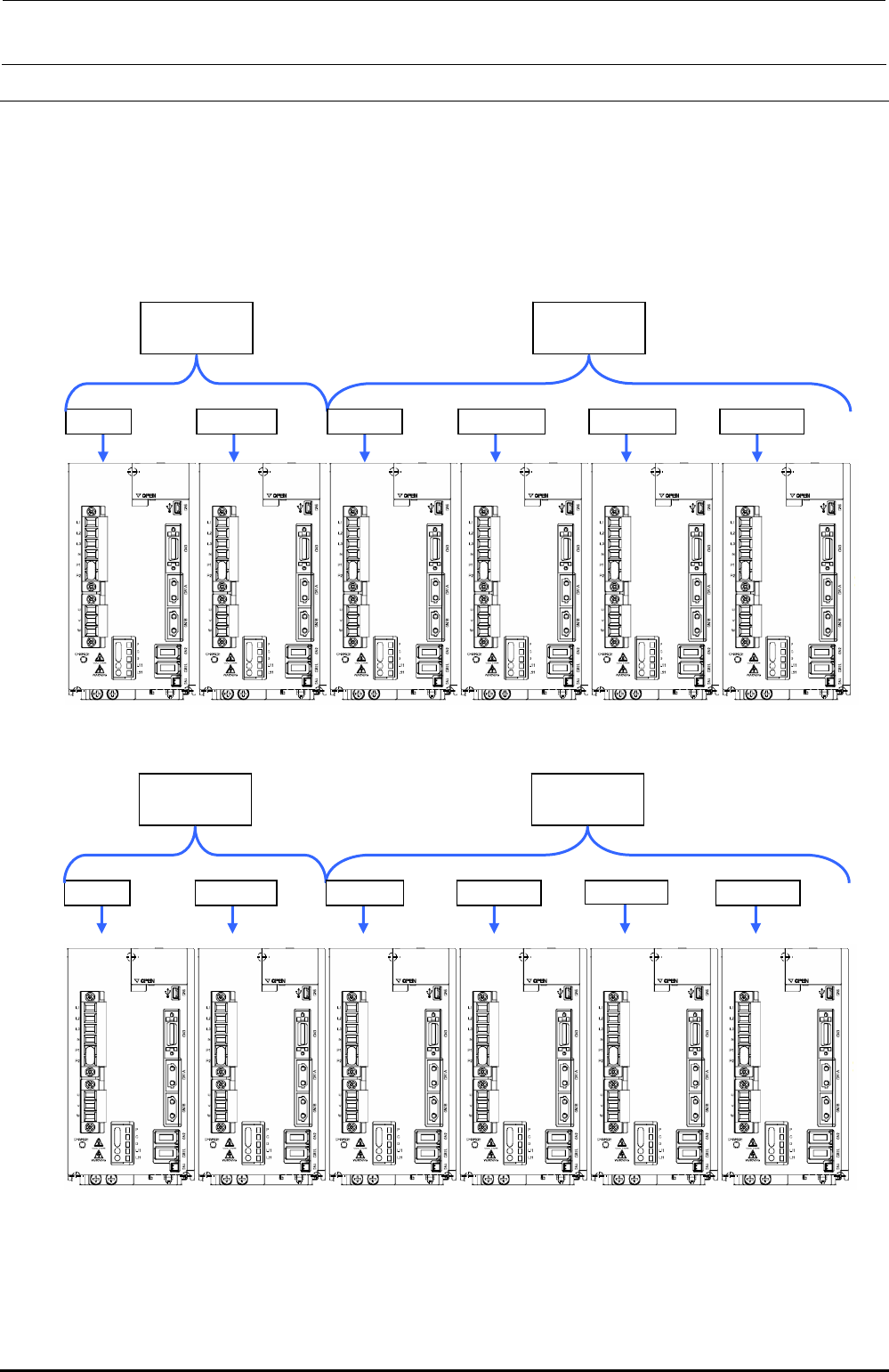
13-5-1. Structure of X-Y Unit
For the AC servo amplifiers, four AC servo amplifiers that drive the X-axis and eight AC servo
amplifiers that drive the Y-axis (twelve amplifiers in total) are mounted.
40104695
X-axis AMP
40104696
Y-axis AMP
X (LF) X (LR) YL (LF) YR (LF) YL (LR) YR (LR)
Figure 13-5-1-1 Structure of X-Y Unit (Left Side inside Base Frame)
40104695
X-axis AMP
40104696
Y-axis AMP
X (RF) X (RR) YL (RF) YR (RF) YL (RR) YR (RR)
Figure 13-5-1-2 Structure of X-Y Unit (Right Side inside Base Frame)
Rev. 1.00