JUKI FX-3R MAINTENANCE GUIDE.pdf - 第212页
FX-3R Maintenance Guide 13-43 Rev . 1.00 • XL specification Applicable cable Part No. Part name Connector No. Sensor block connection destination Remarks 40047910 IN SENS CABLE ASM SBL1-1 SBL1-S1 40089929 BU PIN-L SENS C…
FX-3R Maintenance Guide
13-42
Rev. 1.00
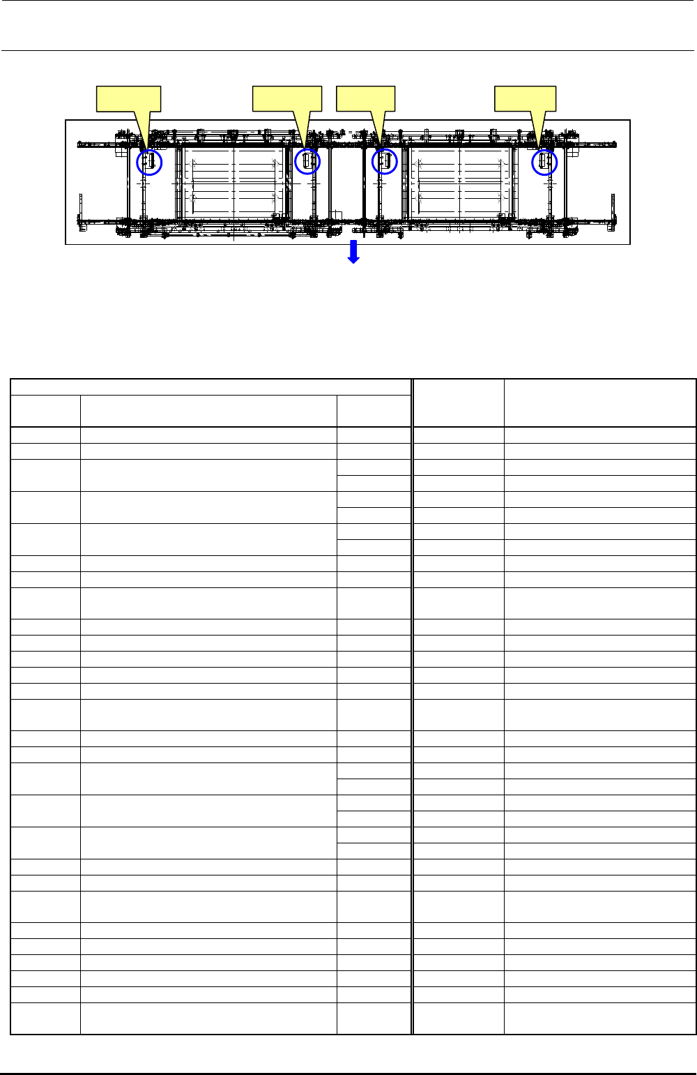
[Connections to sensor block connectors]
Figure 13-7-1-3 Sensor Block Connector Positions
Table 13-7-1-5 Sensor Block Connection Cable Assemblies
• L specification
Applicable cable
Part No. Part name
Connector
No.
Sensor block
connection
destination
Remarks
40047910 IN SENS CABLE ASM SBL1-1 SBL1-S1
−−−−− −−−−−−−−−−−−−−−−−−−−−−− −−−−− SBL1-S2
SBL1-3 SBL1-S3
40047912 WAIT-L SENS CABLE ASM
SBL1-4 SBL1-S4
SBL1-5 SBL1-S5
40047913 STOP-L SENS CABLE ASM
SBL1-6 SBL1-S6
SBL1-7 SBL1-S7
40047914 COUT-L SENS CABLE ASM
SBL1-8 SBL1-S8
40047915 BU ORG-L SENS CABLE ASM SBL2-1 SBL2-S1
40047916 BU LOCK-L SENS CABLE ASM SBL2-2 SBL2-S2
40065185
40065186
CONV STOPPER DETECT CBL LONG ASM
CONV STOPPER DETECT CBL SHORT ASM
SB2-3
SB2-3
SBL2-S3
For L → R transport
For R → L transport
40047917 TPN-L SENS CABLE ASM SBL2-4 SBL2-S4
40047918 AWC-L SENS CABLE ASM SBL2-5 SBL2-S5
−−−−− −−−−−−−−−−−−−−−−−−−−−−− −−−−− SBL2-S6 Not used
−−−−− −−−−−−−−−−−−−−−−−−−−−−− −−−−− SBL2-S7 Not used
−−−−− −−−−−−−−−−−−−−−−−−−−−−− −−−−− SBL2-S8 Not used
40047906 SBL2 RELAY CABLE ASM
Relay cable between SBL1 and
SBL2
40047920 OUT SENS CABLE ASM SBR1-1 SBR1-S1
−−−−− −−−−−−−−−−−−−−−−−−−−−−− −−−−− SBR1-S2
SBR1-3 SBR1-S3
40047922 WAIT-R SENS CABLE ASM
SBR1-4 SBR1-S4
SBR1-5 SBR1-S5
40047923 STOP-R SENS CABLE ASM
SBR1-6 SBR1-S6
SBR1-7 SBR1-S7
40047924 COUT-R SENS CABLE ASM
SBR1-8 SBR1-S8
40047925 BU ORG-R SENS CABLE ASM SBR2-1 SBR2-S1
40047926 BU LOCK-R SENS CABLE ASM SBR2-2 SBR2-S2
40065186
40065185
CONV STOPPER DETECT CBL SHORT ASM
CONV STOPPER DETECT CBL LONG ASM
SB2-3
SB2-3
SBR2-S3
For L → R transport
For R → L transport
40047927 TPN-R SENS CABLE ASM SBR2-4 SBR2-S4
40047928 AWC-R SENS CABLE ASM SBR2-5 SBR2-S5
−−−−− −−−−−−−−−−−−−−−−−−−−−−− −−−−− SBR2-S6 Not used
−−−−− −−−−−−−−−−−−−−−−−−−−−−− −−−−− SBR2-S7 Not used
−−−−− −−−−−−−−−−−−−−−−−−−−−−− −−−−− SBR2-S8 Not used
40047907 SBR2 RELAY CABLE ASM
Relay cable between SBR1 and
SBR2
装置正面側
SBL1 SBL2 SBR2 SBR1
Front of machine

FX-3R Maintenance Guide
13-43
Rev. 1.00
• XL specification
Applicable cable
Part No. Part name
Connector
No.
Sensor block
connection
destination
Remarks
40047910 IN SENS CABLE ASM SBL1-1 SBL1-S1
40089929 BU PIN-L SENS CABLE ASM SBL1-2 SBL1-S2
SBL1-3 SBL1-S3
40047912 WAIT-L SENS CABLE ASM
SBL1-4 SBL1-S4
SBL1-5 SBL1-S5
40047913 STOP-L SENS CABLE ASM
SBL1-6 SBL1-S6
SBL1-7 SBL1-S7
40047914 COUT-L SENS CABLE ASM
SBL1-8 SBL1-S8
40047915 BU ORG-L SENS CABLE ASM SBL2-1 SBL2-S1
40047916 BU LOCK-L SENS CABLE ASM SBL2-2 SBL2-S2
40089930 BPIN-L RCV SENS CABLE ASM SBL2-3 SBL2-S3
40047917 TPN-L SENS CABLE ASM SBL2-4 SBL2-S4
40047918 AWC-L SENS CABLE ASM SBL2-5 SBL2-S5
−−−−− −−−−−−−−−−−−−−−−−−−−−−− −−−−− SBL2-S6 Not used
−−−−− −−−−−−−−−−−−−−−−−−−−−−− −−−−− SBL2-S7 Not used
−−−−− −−−−−−−−−−−−−−−−−−−−−−− −−−−− SBL2-S8 Not used
40047906 SBL2 RELAY CABLE ASM
Relay cable between SBL1 and
SBL2
40047920 OUT SENS CABLE ASM SBR1-1 SBR1-S1
40089931 BU PIN-R SENS CABLE ASM SBR1-2 SBR1-S2
SBR1-3 SBR1-S3
40047922 WAIT-R SENS CABLE ASM
SBR1-4 SBR1-S4
SBR1-5 SBR1-S5
40047923 STOP-R SENS CABLE ASM
SBR1-6 SBR1-S6
SBR1-7 SBR1-S7
40047924 COUT-R SENS CABLE ASM
SBR1-8 SBR1-S8
40047925 BU ORG-R SENS CABLE ASM SBR2-1 SBR2-S1
40047926 BU LOCK-R SENS CABLE ASM SBR2-2 SBR2-S2
40089932 BPIN-R RCV SENS CABLE ASM SBR2-3 SBR2-S3
40047927 TPN-R SENS CABLE ASM SBR2-4 SBR2-S4
40047928 AWC-R SENS CABLE ASM SBR2-5 SBR2-S5
−−−−− −−−−−−−−−−−−−−−−−−−−−−− −−−−− SBR2-S6 Not used
−−−−− −−−−−−−−−−−−−−−−−−−−−−− −−−−− SBR2-S7 Not used
−−−−− −−−−−−−−−−−−−−−−−−−−−−− −−−−− SBR2-S8 Not used
40047907 SBR2 RELAY CABLE ASM
Relay cable between SBR1 and
SBR2
FX-3R Maintenance Guide
13-44
Rev. 1.00
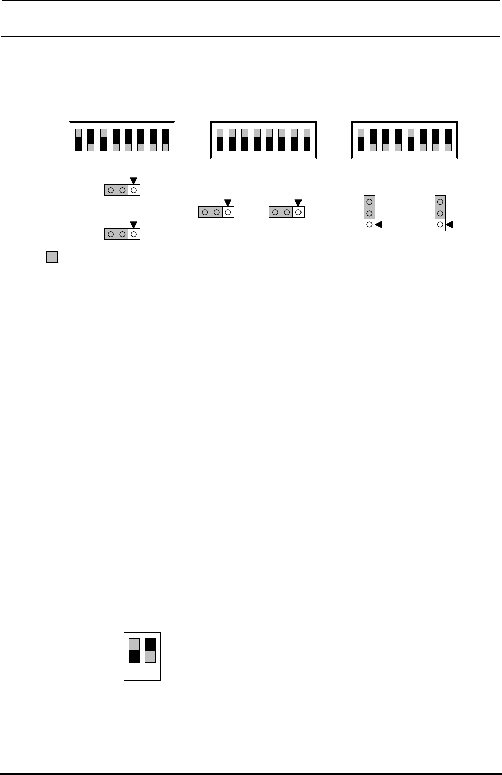
13-7-2. Adjusting the BASE-CARRY Board (40047559)
The jumper switches and DIP switches on the BASE-CARRY board assembly used in the transport
unit have already been set at delivery. However, check that they are set as shown below before
setting the BASE-CARRY board assembly in the transport unit.
Figure 13-7-2-1 DIP switches on BASE-CARRY Board Assembly
13-7-3. Adjusting the Stepping Driver
A stepping motor is used for the transport motor and support table/auto width adjustment motor of
the transport unit.
To rotate the stepping motor correctly, it is necessary to adjust the 5-phase stepping driver.
• IN, Center, OUT transport motor (Transport stepping motor)
HM001320000 5-phase stepping driver
• Support table/width adjustment motor (non-EN specification)
HX004200000 5-phase stepping driver
• Support table/width adjustment motor (EN specification)
HX005450000 5-phase stepping driver
13-7-3-1. Adjusting the Drive Current of the Transport Stepping Motor
<Adjustment Procedure>
c Before starting the adjustment procedure, make sure that the DC power source output
voltage has been properly adjusted.
(For details, see [10]-1, DC Power Source Output Voltage, in the QA table.)
d Turn the transport stepping motor and measure the voltage across [CP1] and [CP2] on the
five-phase stepping driver with a digital voltmeter.
Connect the positive (+) and negative (-) probes of the digital voltmeter to [CP1] and [CP2],
respectively.
e Slowly turn the RUN variable resistor so that the voltage across [CP1] and [CP2] becomes
2.8 ± 0.01 V.
f Set the DIP switches on the step driver as shown in the figure below.
Figure 13-7-3-1-1 DIP Switch Settings
• Specification value
Drive current: 1.4 A ± 0.005 A/phase
(Measured with the voltage across CP1 and CP2. 2.8 V ± 0.01 V)
部がスイッチの設定位置、及びリセ
プ
タクルの取付位置となります。
N
1
2
3
4
5
6
7
8
SW3
N
1
2
3
4
5
6
7
8
SW2
N
1
2
3
4
5
6
7
8
SW4
W1
1
3
W2
1
3
1
3
W3
1
3
W4
3
1
W5
3
1
W6
portion shows the switch set position and receptacle mounting position.
ON
1 2
1.ON
2.OFF