JUKI FX-3R MAINTENANCE GUIDE.pdf - 第219页
FX-3R Maintenance Guide 13-50 d Operation board (EN) jumper switch settings Check W1, W2, and W3. • Jumper switch setting (front) W1 W2 W3 1-2 Open 1-2 Short 1-2 Open 3-4 Open 3-4 Open 3-4 Open 5-6 Short 5-6 Open 5-6 Sho…
FX-3R Maintenance Guide
13-49
13-9. Covers
13-9-1. Structure of Operation Unit
The operation unit is composed of the following four kinds of boards.
c 40047520 Operation board front assembly
d 40047542 Operation board rear assembly
For CE marking machines
c 40047543 Operation board front assembly (EN)
d 40047544 Operation board rear assembly (EN)
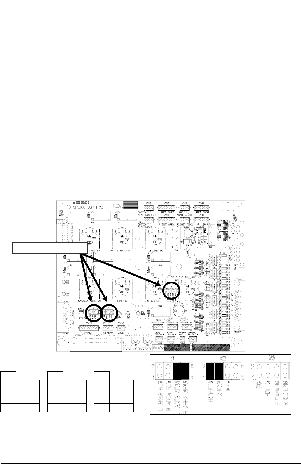
13-9-2. Jumper Switch Settings on the Operation Board Assembly
Check the jumper switch settings on the operation board assembly and the operation board rear
assembly while referring to Figure 13-9-2-1. Additionally, check also the jumper switch settings on
the operation board front assembly (EN) and the operation board rear assembly (EN) while
referring to Figure 13-9-2-2.
c Operation board jumper switch settings
Check W1, W2, and W3.
W1
W2
W3
1-2
Open
1-2
Short
1-2
Open
3-4
Open
3-4
Short
3-4
Open
5-6
Short
5-6
Open
5-6
Open
7-8
Short
7-8
Open
7-8
Open
Mount receptacles at the ■ portions of the straight headers W1, W2, and W3 to make them
short-circuited.
Figure 13-9-2-1 Operation Board Jumper Switch Settings
Rev. 1.00
FX-3R Maintenance Guide
13-50
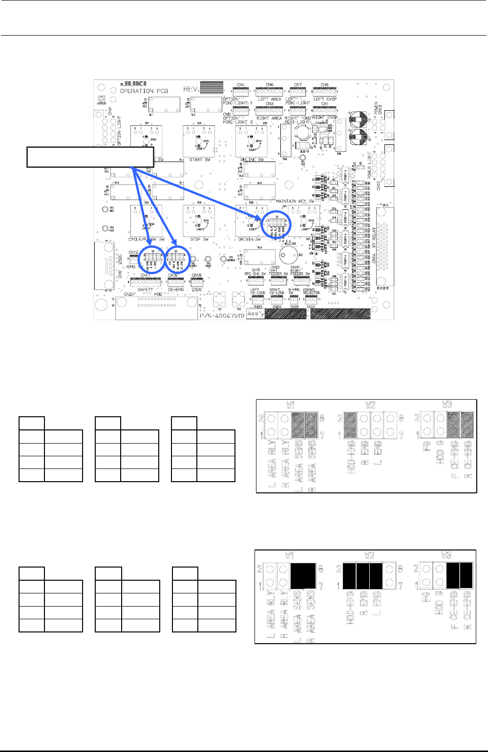
d Operation board (EN) jumper switch settings
Check W1, W2, and W3.
• Jumper switch setting (front)
W1
W2
W3
1-2
Open
1-2
Short
1-2
Open
3-4
Open
3-4
Open
3-4
Open
5-6
Short
5-6
Open
5-6
Short
7-8
Short
7-8
Open
7-8
Short
Mount receptacles at the ■ portions of the straight headers W1, W2, and W3 to make them short-circuited.
• Jumper switch setting (rear)
W1
W2
W3
1-2
Open
1-2
Short
1-2
Open
3-4
Open
3-4
Short
3-4
Open
5-6
Short
5-6
Short
5-6
Short
7-8
Short
7-8
Open
7-8
Short
Mount receptacles at the ■ portions of the straight headers W1, W2, and W3 to make them short-circuited.
Figure 13-9-2-2 Operation board (EN specification) jumper switch settings
Rev. 1.00
FX-3R Maintenance Guide
13-51
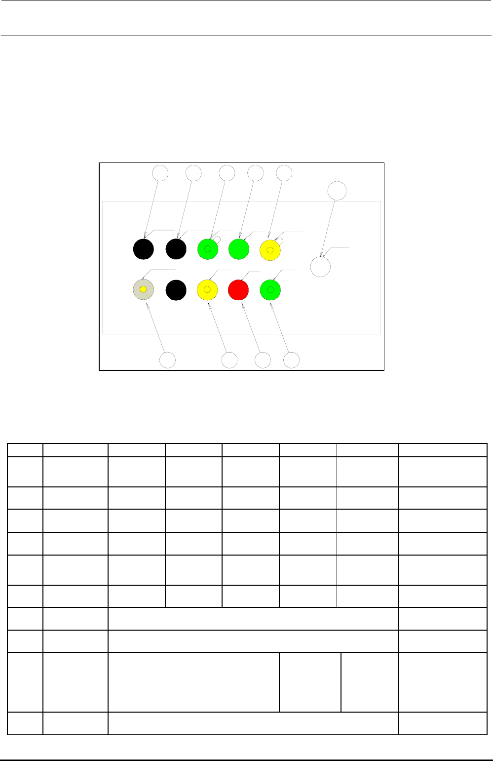
13-9-3. Mounting Switches onto the Operation Switchboard
Mount push-button switches such as start switch or stop switch in the sockets on the operation
switchboard as shown below in compliance with the specifications.
1) Configuration
(1) ST front
Rev. 1.00
LEFT FEEDER
RIGHT FEEDER ONLINE
START SERVO FREE
CONSOLE CHANGE
ORIGIN
STOP
CYCLE
EMERGENCY
SW1
SW2
SW7 SW8 SW3 SW5
SW10
SW9 SW4 SW6
[Option]
Figure 13-9-3-1 Operation Switches (ST Front)
Table 13-9-3-1 List of Operation Switch Replacement Parts (ST Front)
No. Switch name Element Actuator LED Bezel Lenz Remarks
SW1
ONLINE HA005340010 HA005340020 HA005340070 HA00534004A HA00552001B
Bezel is provided with a
cover
SW2
ORIGIN HA005340010 HA005340020 HA00534007A HA005520030 HA00552001A
SW3
START HA005340010 HA005340020
―
HA005520030 HA00552001B
SW4
STOP HA005340010 HA005340020
―
HA005520030 HA005520010
SW5
SERVO FREE HA005340010 HA005340020 HA00534007A HA00534004A HA00552001A
Bezel is provided with a
cover
SW6
CYCLE HA005340010 HA005340020 HA005340070 HA005520030 HA00552001B
SW7
LEFT FEEDER “HX00326000A” is assembled.
SW8
RIGHT FEEDER “HX00326000A” is assembled.
SW9
CONSOLE
CHENGE
40048036 HA005530010 HA00553002A
OPTION
(REAR MONITOR)
If the rear motor OP is not
provided, “HX00326000A”
is mounted.
SW10
EMERGENCY 40092833