JUKI FX-3R MAINTENANCE GUIDE.pdf - 第26页
FX-3R Maintenance Guide 2-8 d After the Z-axis motor has been assembled, obtain the PWB top surface height of the MS parameter. If this value does not fall between − 2 and + 2mm, readjust the positional relationship of t…
FX-3R Maintenance Guide
2-7
2-2. Replacing the Motor
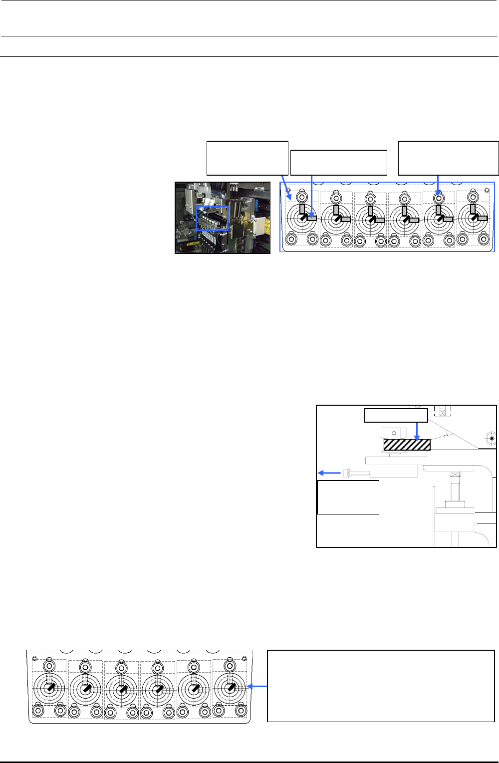
2-2-1. Replacing the Z-Motor
After the Z motor has been replaced, it is absolutely necessary to re-input the MS parameters
related to the Z-axis home position adjustment, Z-axis height, and laser.
(For details of input items, see section 2-7.)
1) Disconnect the Z-motor
cables from the power
connector base and
Z-encoder relay board.
(See also steps 2), 4), 5),
and 7) stated in section
2-1.)
Figure 2-2-1-1 Z-motor Assembly (Top View)
c SM8030312TP
Set screw M3 L=3
d SL6031692TN
SEMS cap bolt with
washer M3×16
40044534
Servomotor 30W
(Z-axis)
2) Loosen the hollow set screws c (×2) of the Z-motor pulley.
3) Remove the SEMS cap bolts d (×3) mounting the motor. Detach the Z-motor by pulling out the
pulley.
4) Reassemble the components in the reverse order of disassembly, and adjust the belt tension
as the last step.
<Belt tension adjustment procedure>
Timing belt Z
Pull by the
force of 21.6N
(2.2kgf)
Figure 2-2-1-2 Timing Belt Z
c Put the screw in the tap of the Z-motor and lock the
mounting screw with the screw pulled in the direction
indicated by an arrow with a force of 21.6 N (2.2 kgf)
using a tension gauge.
Tension meter set value (For check)
• Tension meter input value
Weight: 0.9g/m Width: 8.0mm Span: 45mm
• Specification value: 10.5±1N
∗ Apply Loctite 242 to the Z-motor mounting screws
(3 pcs.) and tighten them with a tightening torque of
2.3 N・m.
∗ When tightening the setscrew of the Z-motor pulley, make sure to align the orientation of the
flat part of the Z-motor shaft and the setscrew of the pulley. Tighten the setscrew with a torque
of 0.5 N・m.
When the Z-motor pulley is secured at a position where
the marking on the shaft is located at 2-o’clock position
as shown in the figure on the left or the shaft D cut
surface is located at a position as shown in the figure
with the Z-axis raised to its uppermost position, this
becomes the conditions for item d.
Figure 2-2-1-3 Z-motor Pulley Assembling Method
Rev. 1.00
FX-3R Maintenance Guide
2-8
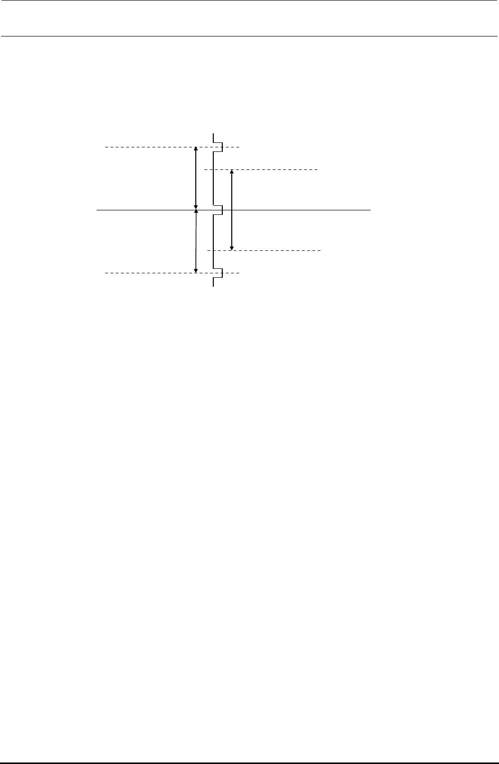
d After the Z-axis motor has been assembled, obtain the PWB top surface height of the MS
parameter.
If this value does not fall between −2 and +2mm, readjust the positional relationship of the
Z-motor axis and the ball screw, obtain the MS parameter again, and check to make sure that
the PWB top surface height falls between −2 and +2mm.
Stroke for one
rotation of the
Z-axis ball screw
6 mm
−
2 to
+
2 mm
Stable area
Z-phase signal of the
Z-motor encoder
Figure 2-2-1-4 Z-phase signal of the Z-motor encoder
【Origin Return Operation】
The Z-axis is rotated upward to make it in contact with the stopper. After that, when the torque
generated by the motor reaches the set torque threshold value, the Z-axis is rotated downward
and the 1st Z-phase is determined to the origin.
Rev. 1.00
FX-3R Maintenance Guide
2-9
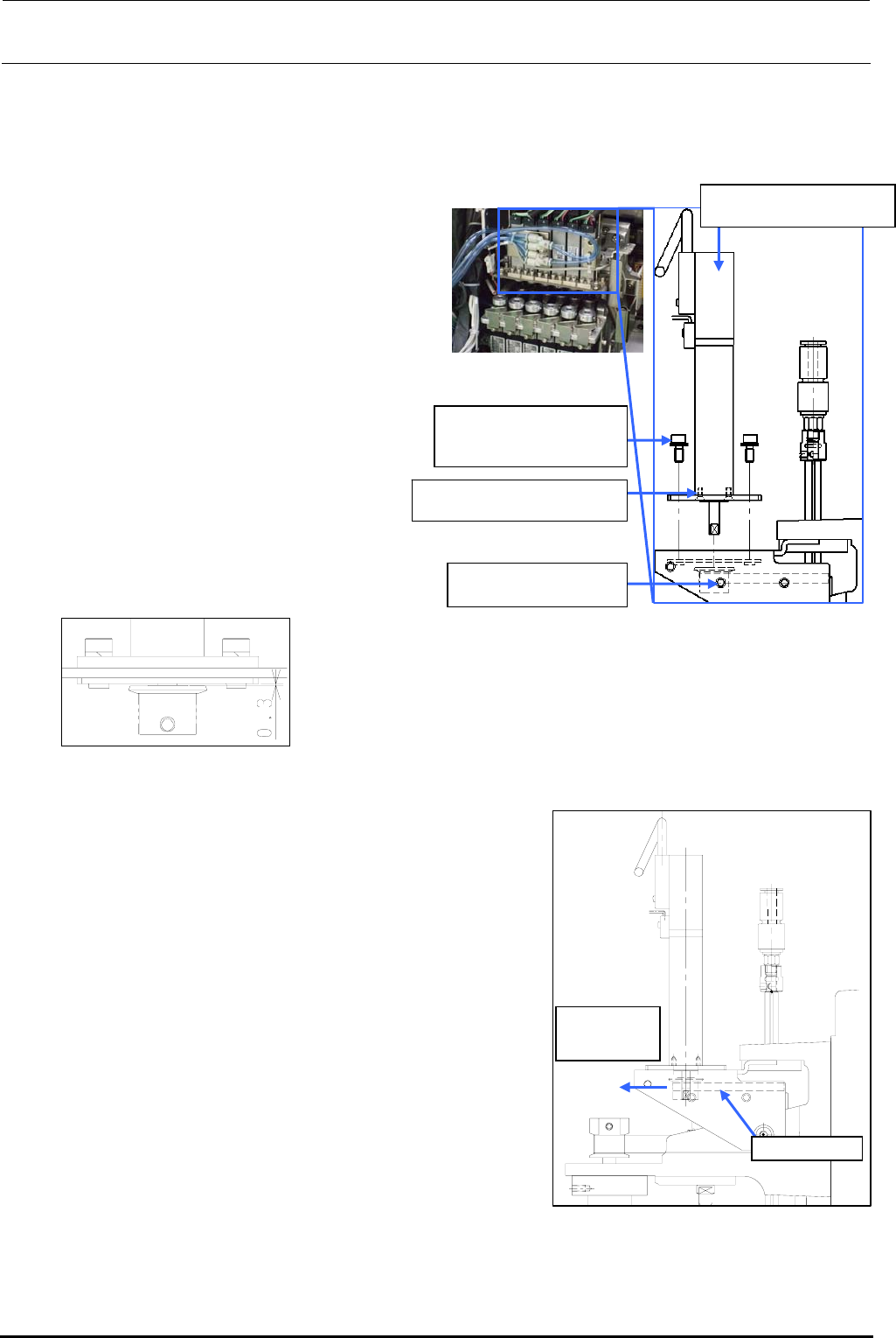
2-2-2. Replacing the θ-Motor
After the θ-motor has been replaced, it is absolutely necessary to re-input the MS parameters
related to the axis home. (For details of input items, see section 2-7.)
1) Disconnect the motor cables from the
servo amplifier board.
(See also steps 2), 3), 8), 9), and 10)
stated in section 2-1.)
Rev. 1.00
2) Loosen the set screws c (hollow set
screws (×1)) of the T pulley.
3) Remove the motor mounting screws d
(SEMS cap bolts (×4)) and pull out the
pulley to detach it.
4) Remove the flat head screws e (×2)
and detach the TM flange.
5) Reassemble the components in the
reverse order of disassembly.
∗ Apply Loctite 242 to the flat head
screws e and tighten them with a
tightening torque of 0.14 N・m.
c SM8030312TP
Set screw M3 L=3
40044533
Servomotor 10W (θ-axis)
SM1020501SC
Flat head screws M2 L=5
6) Follow the steps below to adjust the belt
tension.
<Belt tension adjustment procedure>
c Make a ring using a tie-up band or belt at the top end
of the T pulley of the θ-motor. Hang the bar tension on
this ring. With the bar tension kept pulled with a force
of 12.7N (1.3kgf), secure the T pulley using the
mounting screws.
Tension meter set value (For check)
• Tension meter input value
Weight: 0.9g/m Width: 4.0mm Span: 38.2mm
• Specification value: 6.5±1N
∗ Apply Loctite 242 to the θ-motor mounting screws (2
pcs.) and tighten them with a tightening torque of 2.3
N・m.
∗ When tightening the setscrew of the T pulley, make
sure to align the orientation of the flat part of the
θ-motor shaft and the setscrew of the pulley. Tighten
the setscrew with a torque of 0.5 N・m.
Timing belt T
Pull by the
force of 12.7N
(1.3kgf)
Figure 2-2-2-2 Adjustment of
the θ-motor Belt
Tension
Assemble so that the clearance
between the T pulley and TM nut
plate is 0.3 mm.
d SL6030842TN
SEMS cap bolt with
washer M3×8
Figure 2-2-2-1 θ-motor
e