JUKI FX-3R MAINTENANCE GUIDE.pdf - 第39页
FX-3R Maintenance Guide 3-7 3-3-5. Amplifier Setting Use as it is the amplifier in the factory-settings. Turn on the power supply to make sure that the status shown in the following figure is provided. Rev. 1.00 <LED …
FX-3R Maintenance Guide
3-6
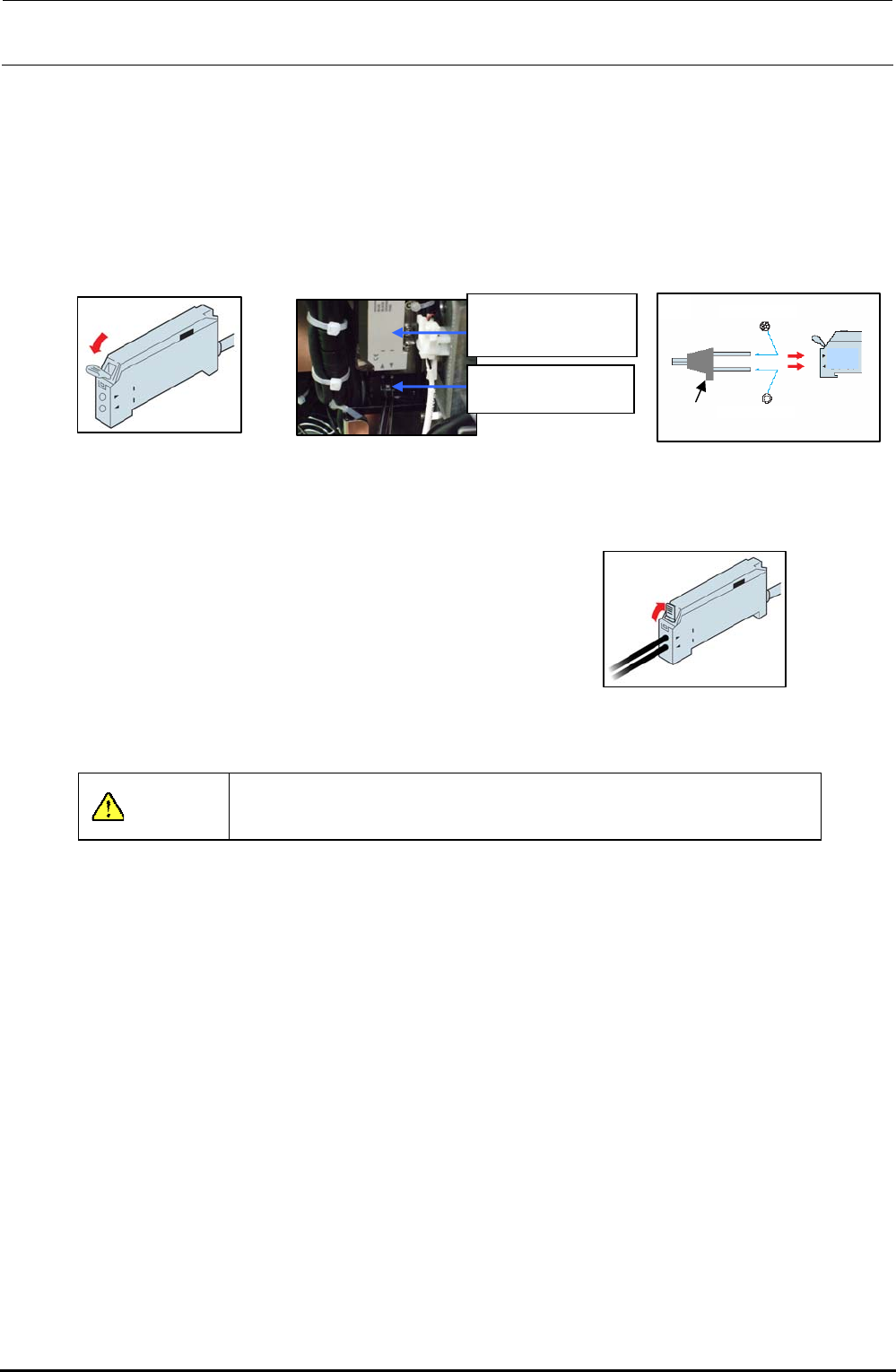
3-3-4. Assembling the Fiber Unit to the Amplifier
1) Open the case cover and flip down the one-touch lock lever.
2) Make the projection faced toward the side where there is no LED and insert the fiber into the
amplifier approx. 13 mm.
After the fiber has been inserted, flip up the lock lever and check that the fiber is not
disconnected. After that, close the case cover.
2)
Projection
Multi-core fibe
r
Single-core fiber
Light receiving side
Light emitting side
Figure 3-3-4-3
Inserting the Fiber
1
)
Figure 3-3-4-1 Amplifier
40047981
Bad mark fiber
amplifier assembly
HD001310030
Fiber unit
Figure 3-3-4-2
Assembling the Amplifier
3) Flip up the one-touch lock lever. Check that the fiber
is not disconnected.
3
)
Figure 3-3-4-4 Fixing the Fiber
CAUTION
Always carry out the wiring work with the power turned OFF.
Rev. 1.00

FX-3R Maintenance Guide
3-7
3-3-5. Amplifier Setting
Use as it is the amplifier in the factory-settings.
Turn on the power supply to make sure that the status shown in the following figure is provided.
Rev. 1.00
<LED status>
L = Light ON operation
Mode switch
Electronic volume position
8 = Maximum sensibility
T = Teaching mode
Figure 3-3-5-1 Bad Mark Sensor Indication
The orange and green LEDs come on simultaneously. → Stable operation status at ON
Only the orange LED comes on. → Unstable operation status at ON
The orange and green LEDs go out simultaneously. → Unstable operation status at OFF
Only the green LED comes on. → Stable operation status at OFF
FX-3R Maintenance Guide
3-8
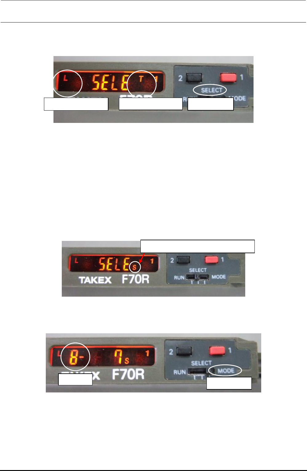
3-3-6. Manual Setting Method for the F70R Fiber Sensor Amplifier
The amplifier setting method is different from the factory-set status. Set this amplifier manually.
- Setting the operation mode
Mode switch
d Operation mode c Sensor function
- Selecting the sensor function (teaching mode setting method)
c Switch the sensor mode switch from [RUN] to [SELECT]. [SELE] appears on the display.
d Each time the button [1] (red) is pressed, the sensor function display changes sequentially in
the order of A, AV, T, TV, L, LV, S, H, and V. Select [T] and reset the mode switch to [RUN].
- Selecting the operation mode (light ON operation setting method)
c Switch the sensor mode switch from [RUN] to [SELECT]. [SELE] appears on the display.
d Each time the button [2] (black) is pressed, the operation mode display changes sequentially in
the order of L, LO, LF, LOF, D, DO, DF, and DOF. Select [L] and reset the mode switch to
[RUN].
- Selecting the electronic volume position
S = Manual setting of operation level
c Switch the sensor mode switch from [RUN] to [SELECT]. [SELE] appears on the display.
d Each time the button [1] (red) is pressed, the sensor function display changes sequentially in
the order of A, AV, T, TV, L, LV, S, H, and V. Select [S].
Blinkin
g
Mode switch
e Switch the sensor mode switch from [SELECT] to [MODE]. The numeric value of the electronic
volume blinks.
f Reset the mode switch from [MODE] to [SELECT].
g Each time the button [1] (red) is pressed, the sensor function display changes sequentially in
the order of A, AV, T, TV, L, LV, S, H, and V. Select [T] and reset the mode switch to [RUN].
Rev. 1.00