JUKI FX-3R MAINTENANCE GUIDE.pdf - 第40页
FX-3R Maintenance Guide 3-8 3-3-6. Manual Setting Method for th e F70R Fiber Sensor Amplifier The amplifier setting method is different from the factory-set status. Set this amplifier manually. - Setting the operation mo…
FX-3R Maintenance Guide
3-7
3-3-5. Amplifier Setting
Use as it is the amplifier in the factory-settings.
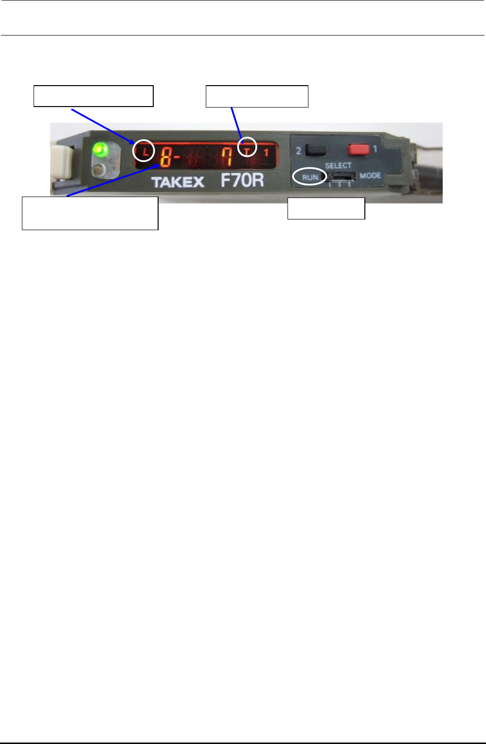
Turn on the power supply to make sure that the status shown in the following figure is provided.
Rev. 1.00
<LED status>
L = Light ON operation
Mode switch
Electronic volume position
8 = Maximum sensibility
T = Teaching mode
Figure 3-3-5-1 Bad Mark Sensor Indication
The orange and green LEDs come on simultaneously. → Stable operation status at ON
Only the orange LED comes on. → Unstable operation status at ON
The orange and green LEDs go out simultaneously. → Unstable operation status at OFF
Only the green LED comes on. → Stable operation status at OFF
FX-3R Maintenance Guide
3-8
3-3-6. Manual Setting Method for the F70R Fiber Sensor Amplifier
The amplifier setting method is different from the factory-set status. Set this amplifier manually.
- Setting the operation mode
Mode switch
d Operation mode c Sensor function
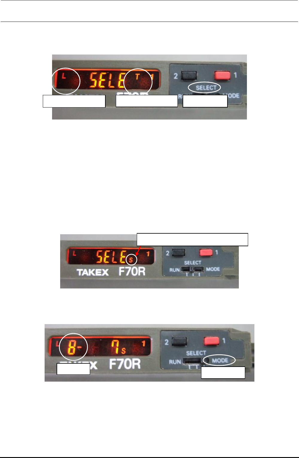
- Selecting the sensor function (teaching mode setting method)
c Switch the sensor mode switch from [RUN] to [SELECT]. [SELE] appears on the display.
d Each time the button [1] (red) is pressed, the sensor function display changes sequentially in
the order of A, AV, T, TV, L, LV, S, H, and V. Select [T] and reset the mode switch to [RUN].
- Selecting the operation mode (light ON operation setting method)
c Switch the sensor mode switch from [RUN] to [SELECT]. [SELE] appears on the display.
d Each time the button [2] (black) is pressed, the operation mode display changes sequentially in
the order of L, LO, LF, LOF, D, DO, DF, and DOF. Select [L] and reset the mode switch to
[RUN].
- Selecting the electronic volume position
S = Manual setting of operation level
c Switch the sensor mode switch from [RUN] to [SELECT]. [SELE] appears on the display.
d Each time the button [1] (red) is pressed, the sensor function display changes sequentially in
the order of A, AV, T, TV, L, LV, S, H, and V. Select [S].
Blinkin
g
Mode switch
e Switch the sensor mode switch from [SELECT] to [MODE]. The numeric value of the electronic
volume blinks.
f Reset the mode switch from [MODE] to [SELECT].
g Each time the button [1] (red) is pressed, the sensor function display changes sequentially in
the order of A, AV, T, TV, L, LV, S, H, and V. Select [T] and reset the mode switch to [RUN].
Rev. 1.00
FX-3R Maintenance Guide
3-9
3-4. Replacing the HMS
3-4-1. Replacing the HMS Head
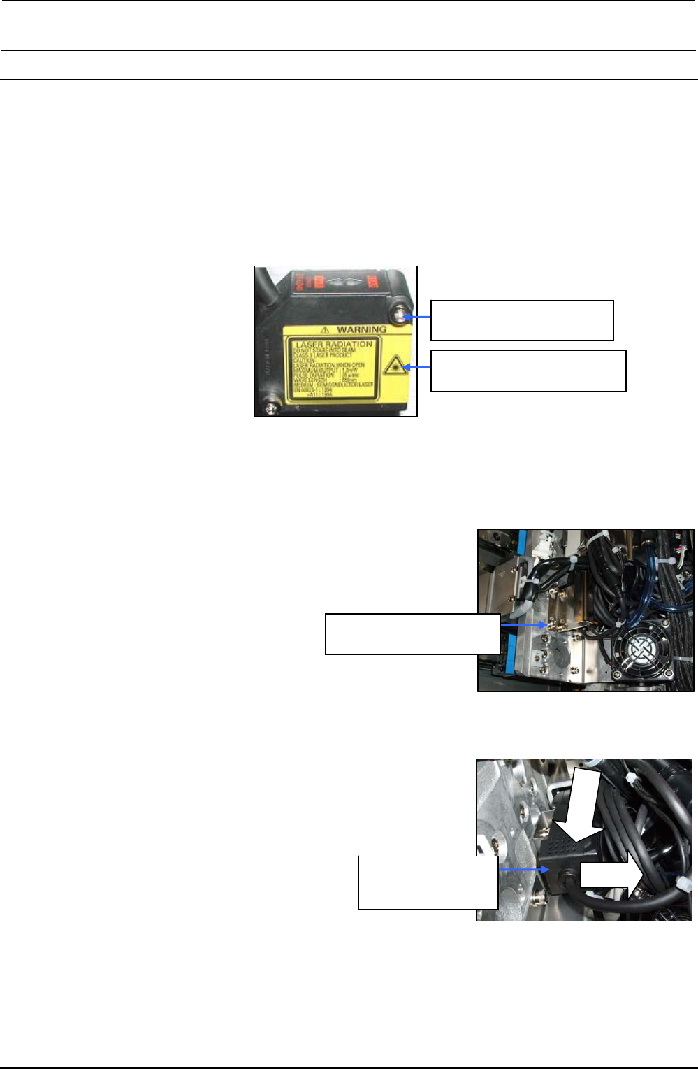
1) Remove the cap bolts c (×2) to detach the HMS head. (The following Figure shows the HMS
head for the LF and RR heads.)
2) Reassemble the parts and components in the reverse order of disassembly. In the same
manner as described above, detach the HMS head from the LR and RF heads.
c SM6032002TN
SEMS cap bolt M3×20
40047874
Height sensor unit assembly
Figure 3-4-1-1 Replacing the HMS Head
3-4-2. Replacing the Amplifier
1) Remove the cap bolts c (×2) to detach the head handle.
∗ When an optional bad mark reader is mounted, detach
the fiber unit from the bad mark amplifier.
c SM6032002TN
SEMS cap bolt M3×20
Figure 3-4-2-1 Detaching the Head Handle
2) Detach the amplifier while keeping the amplifier pushed
downward. (The following Figure shows the amplifier for the
LF and RR heads.)
cLower
dPull
40047874
Height sensor unit
assembly
3) Reassemble the parts and components
in the reverse order of disassembly.
In the same manner as described above,
detach the amplifier from the LR and RF
heads.
Figure 3-4-2-2 Detaching the Amplifier
Rev. 1.00