JUKI FX-3R MAINTENANCE GUIDE.pdf - 第44页
FX-3R Maintenance Guide 3-12 3-6. Replacing the ZT-Driver Board 3-6-1. Replacing the ZT-Driver Board 1) Refer to section 2-1, “ Replacing the Head Unit ” , and steps 1) to 6), 14), and 16) in “ Adjustment after replaceme…
FX-3R Maintenance Guide
3-11
3-5. Replacing the Head Board
3-5-1. Replacing the Head Main Board
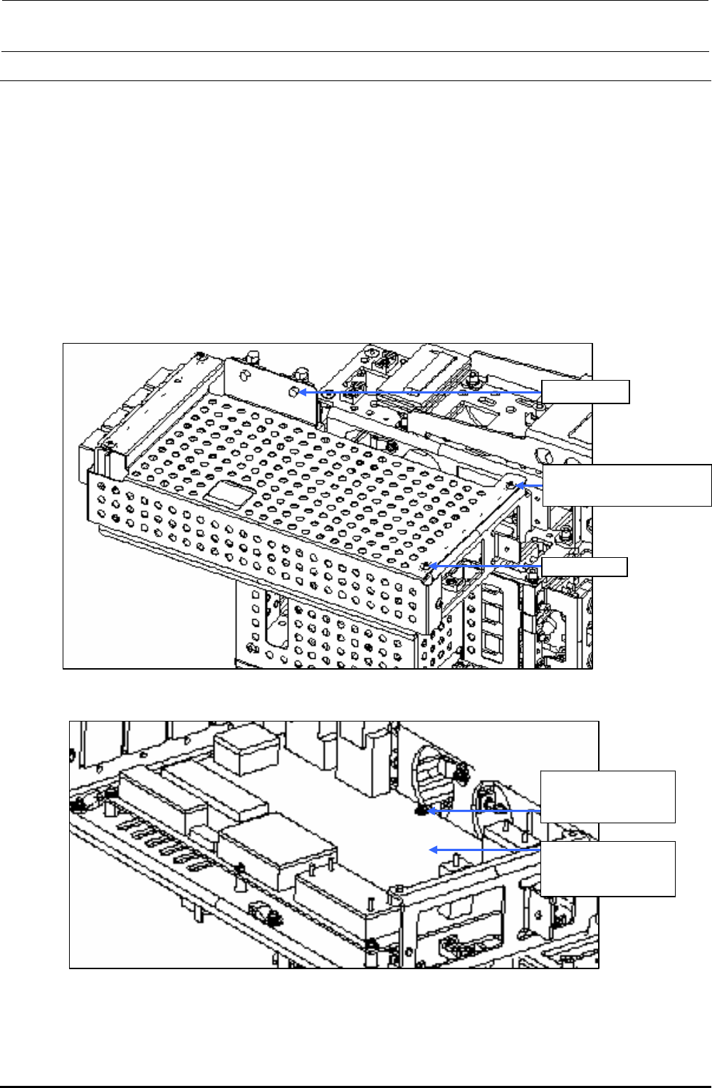
1) Remove the round screws c (×6) and clamps d (×2) to detach the main cover.
2) Disconnect various connectors and remove the SEMS cap bolts e (×6) to detach the head
main board.
3) Reassemble the parts and components in the reverse order of disassembly.
Since the head main board is delivered after it has been adjusted correctly, no adjustment work
is required.
∗ Follow the steps stated in“Head Vacuum Level and Temperature Sensor Output Level”on
page 1-4 for the QA table, only if any fault is found.
c SM3040652TN
Round screw M4×6
Clamp d
Main cover
Figure 3-5-1-1 Main Cover
e SL4030691SC
SEMS cap bolts
M3×6
40047506
Head main board
assembly
Figure 3-5-1-2 Replacing the Head Main Board
Rev. 1.00
FX-3R Maintenance Guide
3-12
3-6. Replacing the ZT-Driver Board
3-6-1. Replacing the ZT-Driver Board
1) Refer to section 2-1, “Replacing the Head Unit”, and steps 1) to 6), 14), and 16) in “Adjustment
after replacement” of Chapter 2.
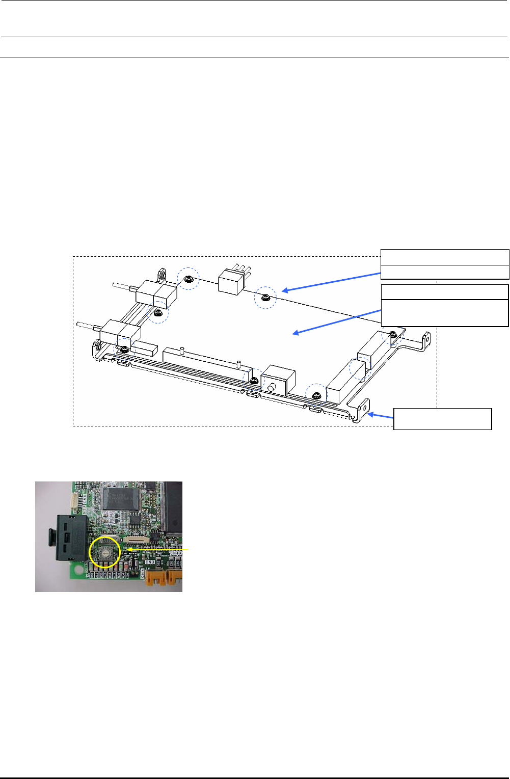
2) Remove the SEMS cap bolts c (×8) from the ZT-driver support to detach the ZT-driver board.
∗ The trimmer on the ZT-driver board needs to be adjusted. Adjust the trimmer while
referring to section 13-6, Z-θ Unit
3) Reassemble the parts and components in the reverse order of disassembly.
c SL4030691SC
SEMS cap bolts M3×8
40044535
4-axis integrated type
servo amplifier
ZT-driver support
Figure 3-6-1-1 Replacing the Driver Board
Trimmer
Rev. 1.00
FX-3R Maintenance Guide
4-1
DANGER
To prevent any trouble caused by accidental machine start, always
shut-down the power before starting the maintenance and
adjustment work.
[4] OCC ASSEMBLY
4-1. Replacing the OCC Assembly
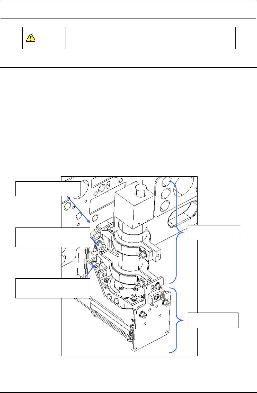
1) Remove the SEMS cap bolts c to detach the lens assembly.
2) The light assembly is secured with the SEMS cap bolts d. Disconnect the connectors and
remove relevant bolts to detach the camera and light assemblies.
3) Reassemble the components in the reverse order of disassembly. (At this time, apply Loctite
242 to the SEMS cap bolts c (×2) and M4-SEMS cap bolts (×2).)
4) After the lens assembly has been replaced, it is absolutely necessary to adjust the focus and
input the MS parameters. After the light assembly has been replaced, it is necessary to adjust
OCC light. (See 4-8, List of Readjustment Items after Replacement.)
LF/RR head: XM base A
LR/RF head: XM base B
40046815
OCC lens assembly
40046816
OCC light assembly
c SL6052092TN
SEMS cap bolt with washer
M5×20
d SL6041292TN
SEMS cap bolt with washer
M4×12
Figure 4-1-1 OCC Assembly
Rev. 1.00