JUKI FX-3R MAINTENANCE GUIDE.pdf - 第55页
FX-3R Maintenance Guide 5-2 Rev. 1.00 5-2. Replacing the Transport Pulley Two kinds of transport pulleys are available. I f the mounting position is changed or the pulle y is mounted incorrectly, this may cause incorrect…
FX-3R Maintenance Guide
5-1
Rev. 1.00
DANGER
To prevent any trouble caused by accidental machine start, always
shut-down the power before starting the maintenance and
adjustment work.
[5] BOARD TRANSPORT UNIT
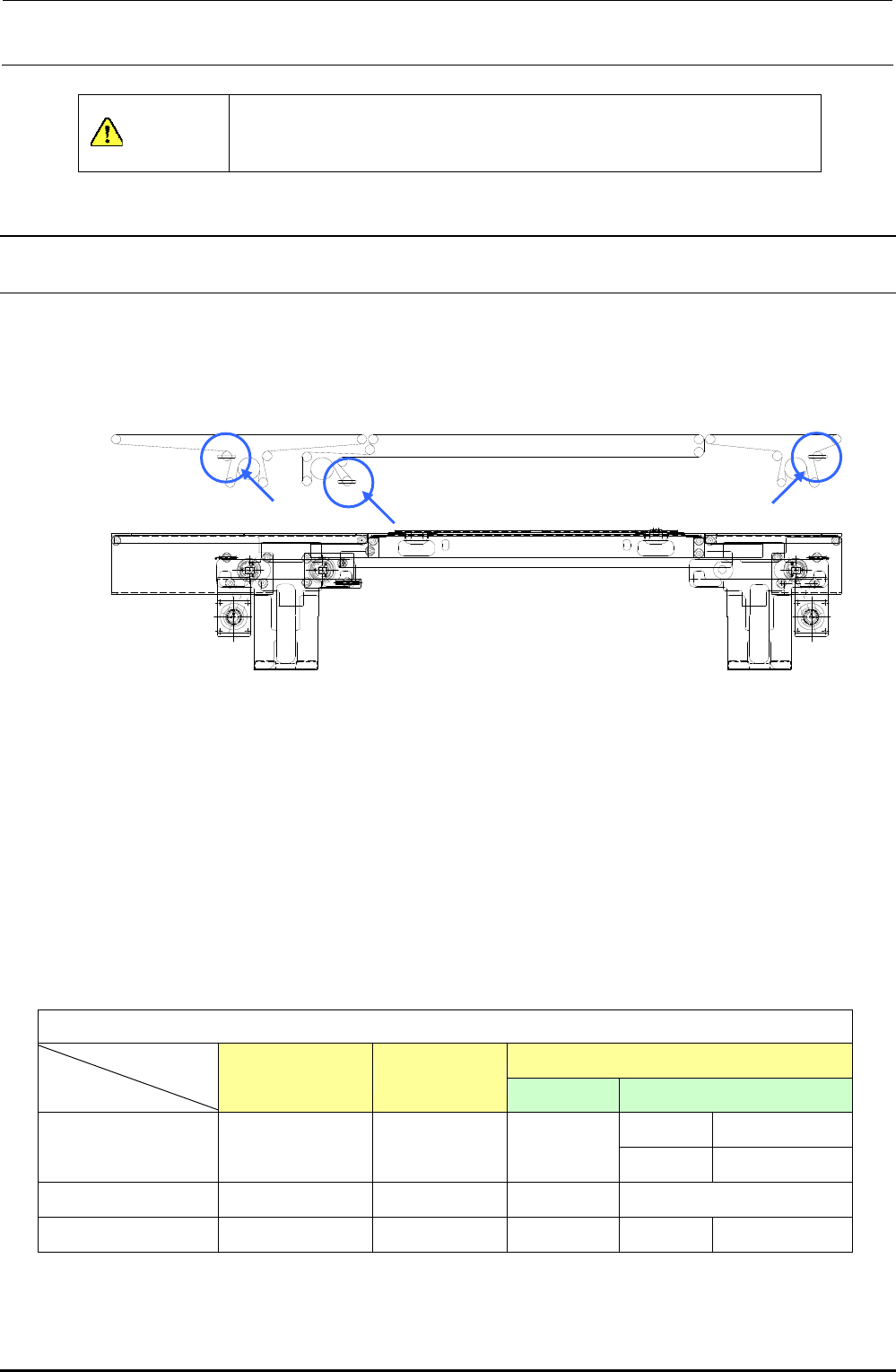
5-1. Replacing the Transport Belt
1) Loosen the transport belt tension adjustment pulley. (Locations indicated by arrows in the
figure below)
Figure 5-1-1 PWB Transport Block and Transport Belt
2) Replace the belt with the one shown in Table 5-1-1.
3) To provide appropriate belt tension, measure the length of the belt with no tension exerted, and
adjust the position of the transport pulley along the slot so that the belt length increases by
0.5%.
<Adjustment procedure>
Use a pencil or similar tool to put two marks, which are 200mm apart from each other, on the belt.
Move the transport pulley to exert tension so that the distance increases to 201 mm.
Table 5-1-1 Transport Belt Part No.
[List of Replacement Parts]
IN/OUT
STATION JOINT
ST Extended transport
150 mm 40073709
L PWB specification
40046935 40046936 40046937
250 mm 40073708
L-wide OP (Note)
40046935 40046936 40046938
−
XL PWB specification
40092069 40092061 40092060 200 mm 40092062
(Note) L-wide is the option specification.
IN/OUT-rail
S-rail
JOINT-rail
FX-3R Maintenance Guide
5-2
Rev. 1.00
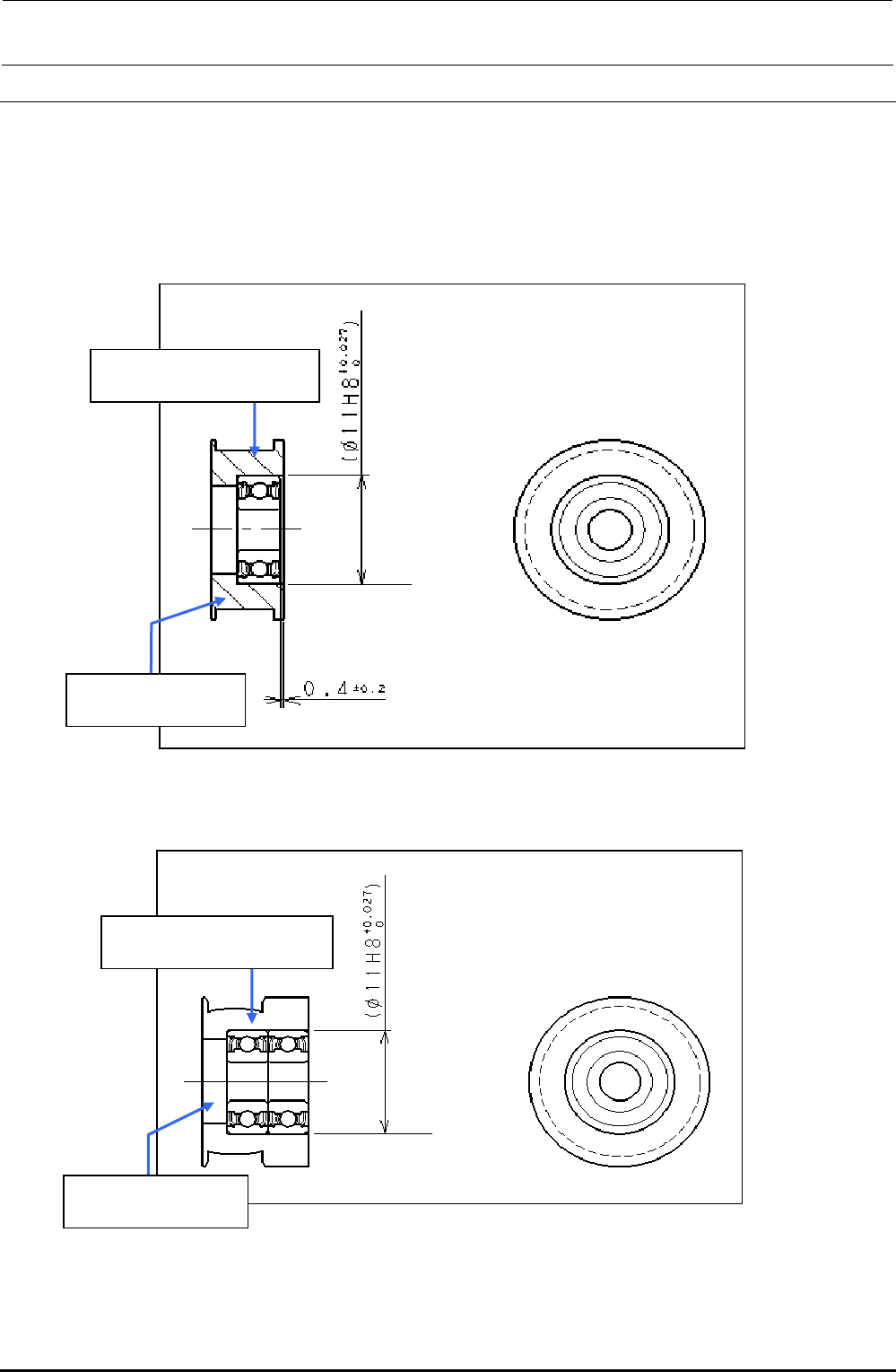
5-2. Replacing the Transport Pulley
Two kinds of transport pulleys are available. If the mounting position is changed or the pulley is
mounted incorrectly, this may cause incorrect pulley rotation or incorrect alignment of the transport
belt, resulting in wear on the belt.
Always refer to relevant mounting procedure when mounting the transport pulley.
5-2-1. Transport Pulley A Assembly: E21117150A0
Figure 5-2-1-1 Transport Pulley A Assembly
5-2-2. Transport Pulley B Assembly: E20897210A0
Figure 5-2-2-1 Transport Pulley B Assembly
SB104000100
Roll bearing Q’ty: 1
E2111715000
Transport pulley A Q’ty: 1
E2089721000
Transport pulley B Q’ty: 1
SB104000100
Roll bearing Q’ty: 2
FX-3R Maintenance Guide
5-3
Rev. 1.00
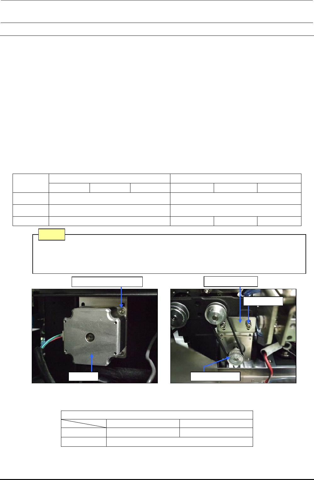
5-3. Replacing the STATION, IN, OUT, and JOINT Motors
1) Disconnect the connector of the motor relay cable.
2) Loosen the screws f fixing the motor bracket d to detach the drive belt from the motor pulley
e.
3) Loosen the motor fixing screws g and detach the motor c.
Reassemble the parts and components in the reverse order of disassembly. (i.e. from step 3) to step
1)). While reassembling, the following adjustment is required.
<Adjustment> For details, see “PWB Transport” in the QA table.
1) The end face of the motor pulley shall be aligned with the end of the motor shaft.
2) Tension adjustment of the timing belt
• Specification value: 17.5 to 21.5N⋅m
Use UNITTA's acoustic belt tension meter for measurement. Enter the following values
to the tension meter and make a measurement:
Table 5-3-1 Transport Motor Tension Adjustment Values
L specification XL specification
STATION IN/OUT JOINT STATION IN/OUT JOINT
Weight 2.5
←
Width 6.0
←
Span 90 90 182 160
Figure 5-3-1 Station Motor (L specification)
Table 5-3-2 Replacement Parts of Transport Motor
[List of Replacement Parts]
STATION/IN/OUT JOINT
L specification 40048074 ∗1 40048075 ∗2
XL specification 40048075
∗1 The transport motor was changed from the motor (E93417290A0) and these motors have the interchangeability.
∗2 The transport motor was changed from the motor (E93408550A0) and these motors have the interchangeability.
Belt (tension) is stretched excessively. → Torque of the drive shaft increases.
Belt (tension) is loosened excessively. → Teeth on the timing pulley are skipped.
(Noise is produced.)
Note
Motor bracket d
Screws f
Motor pulley e
Motor fixing screw g
Motor c