JUKI FX-3R MAINTENANCE GUIDE.pdf - 第61页
FX-3R Maintenance Guide 5-8 Rev. 1.00 XL specification Figure 5-5-3-5 Sensor Amp lifier with XL Specification <Setting procedure> 1) Change the SET/RUN change-over switch g to the “SET” mode. 2) Press the operati…
FX-3R Maintenance Guide
5-7
Rev. 1.00
5-5-3. Adjusting the Sensitivity of the WAIT/STOP/C-OUT Sensor
L specification
<Changing the output>
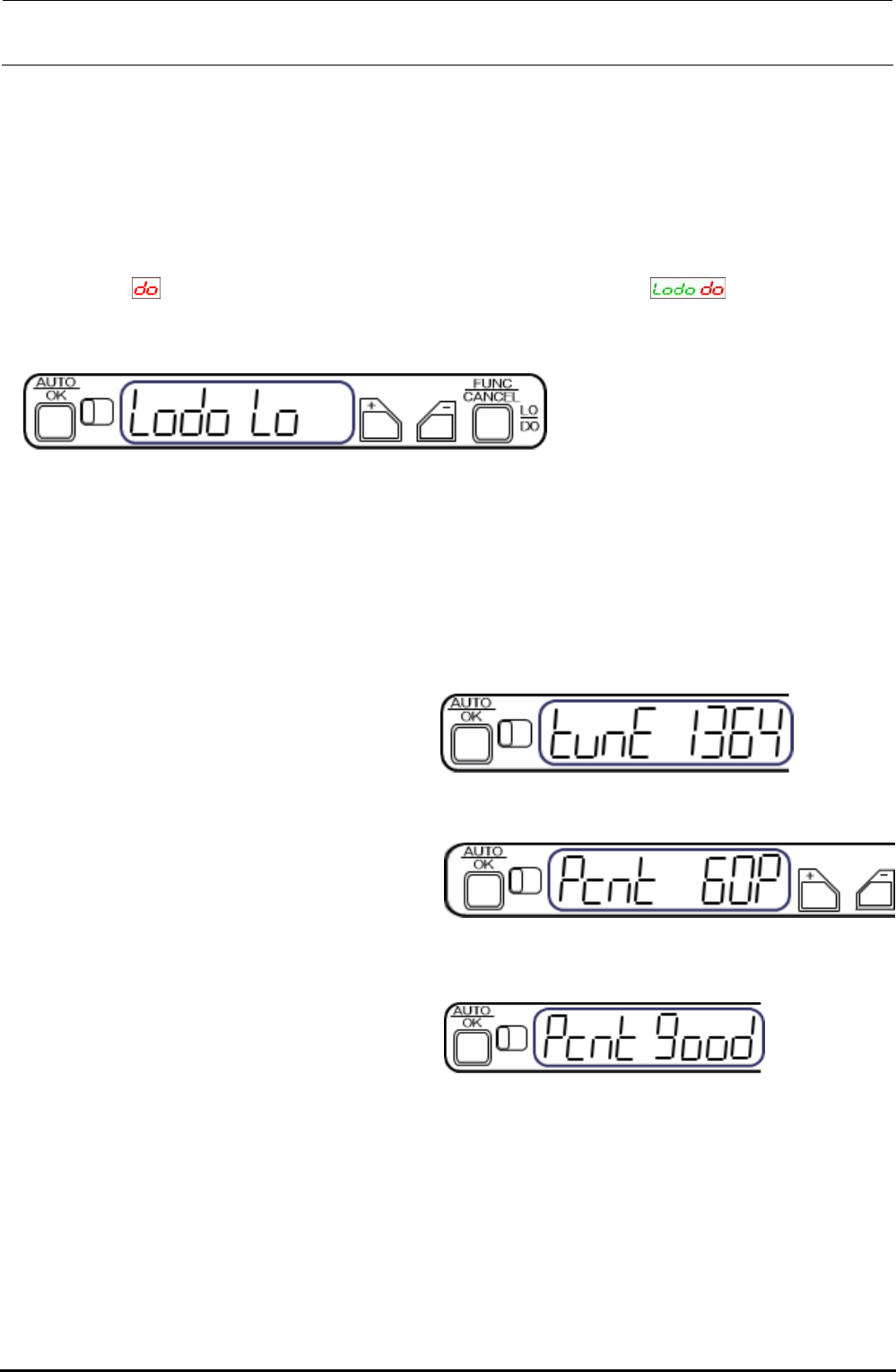
The output change-over setting is changed from LO (output is turned ON when the light is received)
to DO (output is turned ON when the light is interrupted).
1) Keep the [FUNC/CANCEL] button pressed for 3 sec. or longer.
2) Select
with the [+] or [−] button. (Digital indicator on amplifier, )
3) Pressing the [AUTO/OK] button will complete the output change-over setting. (Note: When the
above indicator is left without any operation, the indicator is returned to the normal indication.)
Figure 5-5-3-1 Sensor Amplifier
<Percentage tuning>
Specify a percentage (%) based on the current light receiving level. This level is determined to the
set value.
∗ Driven rail can be located at any position during percentage tuning setting.
• The set value is determined to “60%”.
1) Press the [AUTO/OK] button once
momentarily.
Figure 5-5-3-2 [AUTO/OK] Button
2) Set a threshold value level percentage
with the [+] or [−] button.
CAUTION: At this time, do not shut
down the sensor.
Figure 5-5-3-3 Setting of Threshold Value
• The threshold value is 60%.
3) Press the [AUTO/OK] button.
“Pcnt good” is indicated when the tuning
has been completed.
Figure 5-5-3-4 Completion of Tuning
∗ If an error occurs during tuning, take the actions shown below.
If an error is shown during tuning, press the [FUNC/CANCEL] button, and then press the
[CANCEL] button. Review the status, and then perform the percentage tuning again or restart the
tuning.
∗ Do not put any workpiece during tuning.
∗ Every time the auto width adjustment is performed, the sensor amplifier is then reset. 60%-set
value is changed according to each transport width.
FX-3R Maintenance Guide
5-8
Rev. 1.00
XL specification
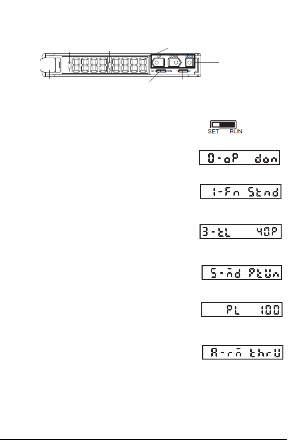
Figure 5-5-3-5 Sensor Amplifier with XL Specification
<Setting procedure>
1) Change the SET/RUN change-over switch g to the “SET”
mode.
2) Press the operation key i to display the operation mode
setup indication (indication is “0-op”). Press the triangle
button i to set the dark ON (don).
3) Press the operation key i to display the detection function
mode setup indication (1-Fn). Press the triangle button i to
set the standard mode (Stnd).
4) Press the square button of the operation key i to display
the threshold value teaching level setup indication (3-tL)
and press the triangle button i to set “40P”.
5) Press the square button of the operation key i to display
the MODE key setup indication (5-Md). Press the triangle
button i to set the power tuning run mode (PtUn).
6) Press the square button of the operation key i to display
the power tuning target value setup indication (PL). Press
the triangle button i to set “100”.
7) Press the yellow button of the operation key i to display
the external input setup indication (A-rM). Press the triangle
button i to set the teaching without transmission
workpiece (thrU).
c
RUN indicator 1 CH
(Orange)
d Main digital display (Red)
e RUN indicator 2 CH
(Orange)
f Sub-digital display (Green)
i Operation key
h Channel change-over switch
g SET/RUN change-over switch
j Lock lever
Change to the
SET mode.
Figure 5-5-3-6 SET Mode
Figure 5-5-3-7 Operation Mode
Figure 5-5-3-8 Detection
Function Mode
Figure 5-5-3-9 Threshold Value
Teaching Level
Figure 5-5-3-10 MODE Key
Setup
Figure 5-5-3-11 Power Tuning
Target Value
Figure 5-5-3-12 External Input
Setup

FX-3R Maintenance Guide
5-9
Rev. 1.00
<Power tuning procedure>
1) Change the SET/RUN change-over switch g to the “RUN”
mode.
2) Set the auto width to “610 mm”. Keep the square button of the operation key i pressed for 3
sec. or longer to perform the power tuning.
At this time, pay special attention so that a portion between the transport rails does not interfere
with the light emitted from the optical fiber suitable for the amplifier being operated.
Change to the RUN
mode.
Figure 5-5-3-13 RUN Mode