JUKI FX-3R MAINTENANCE GUIDE.pdf - 第63页
FX-3R Maintenance Guide 5-10 Rev. 1.00 5-6. Replacing the Stopper Cylinder 1) Remo ve the hexagon nut c . The parts d , e , and f can then be removed. 2) Remo ve the hexagon nut g securing the cylinder . (Tool: Single-en…

FX-3R Maintenance Guide
5-9
Rev. 1.00
<Power tuning procedure>
1) Change the SET/RUN change-over switch g to the “RUN”
mode.
2) Set the auto width to “610 mm”. Keep the square button of the operation key i pressed for 3
sec. or longer to perform the power tuning.
At this time, pay special attention so that a portion between the transport rails does not interfere
with the light emitted from the optical fiber suitable for the amplifier being operated.
Change to the RUN
mode.
Figure 5-5-3-13 RUN Mode
FX-3R Maintenance Guide
5-10
Rev. 1.00
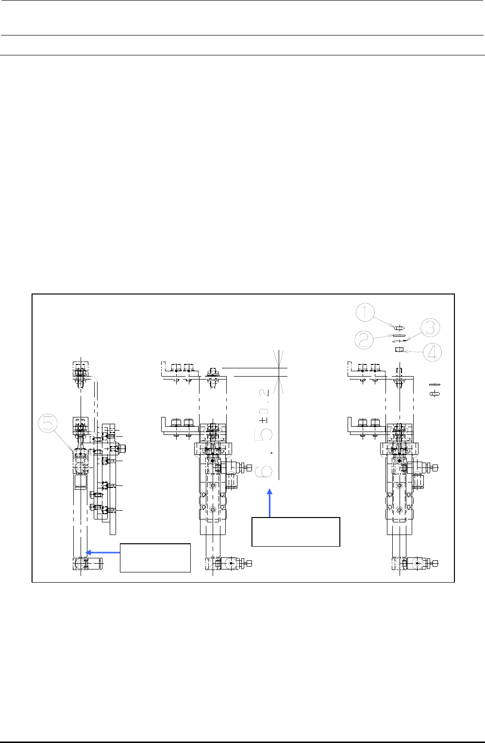
5-6. Replacing the Stopper Cylinder
1) Remove the hexagon nut c. The parts d, e, and f can then be removed.
2) Remove the hexagon nut g securing the cylinder. (Tool: Single-ended wrench, 11-size)
3) Detach the speed controller from the cylinder. (At this time, check what side the speed
controller has been mounted.)
4) When installing a new stopper cylinder, reassemble the components in the order of steps 3) to
1).
At this time, assemble the cylinder so that the orientation of the speed controller is opposite to
that of the stopper tip.
Additionally, assemble the cylinder so that the distance between the end face of the stopper
arm and the end face of the rod becomes that shown in the Figure below.
5) After the components have been reassembled, supply air (0.49 MPa) to check that the stopper
cylinder moves smoothly.
Figure 5-6-1 Stopper Cylinder
Extrusion amount
of the cylinder rod
PA1004514A0
Air cylinder
FX-3R Maintenance Guide
5-11
Rev. 1.00
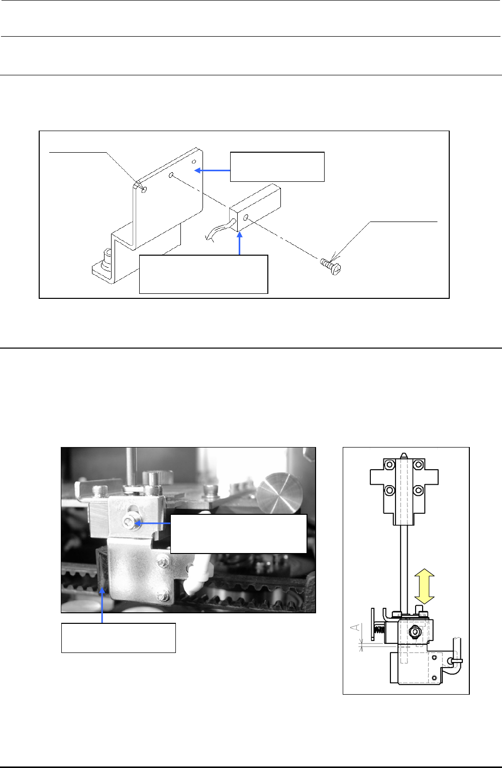
5-7. Replacing the Support Table Home Position Sensor
(BU Home Position Sensor)
1) Detach the sensor from the sensor bracket.
2) Adjust the distance between the sensor and sensor dog to 1 mm.
Figure 5-7-1 BU Home Position Sensor
5-8. Replacing the T-PIN Sensor (Optional)
1) Remove the adjustment screw to detach the sensor bracket and replace the sensor.
When reassembling the components, adjust the position of the sensor bracket by loosening the
adjustment screw and moving the sensor bracket up and down so that the T-PIN sensor is
turned ON when the center ring pin is lowered by 1.5
0
-0.5
mm.
2) Carefully handle the cables.
Figure 5-8-1 T-PIN Sensor
40046962
BU sensor bracket
40002124
Backup table home
position sensor assembly
For tie-band
Screw supplied
with sensor
SL6030692TN
SEMS cap bolt with washer
M3×6
40002122
T-PIN sensor assembly