JUKI FX-3R MAINTENANCE GUIDE.pdf - 第65页
FX-3R Maintenance Guide 5-12 Rev. 1.00 5-9. Replacing the Pusher Y Cylinder (Outer Shape Reference) 1) Remove the parts c to detach the cylinder. As the cylinder is detached, the spring is also then removed. 2) Detach th…
FX-3R Maintenance Guide
5-11
Rev. 1.00
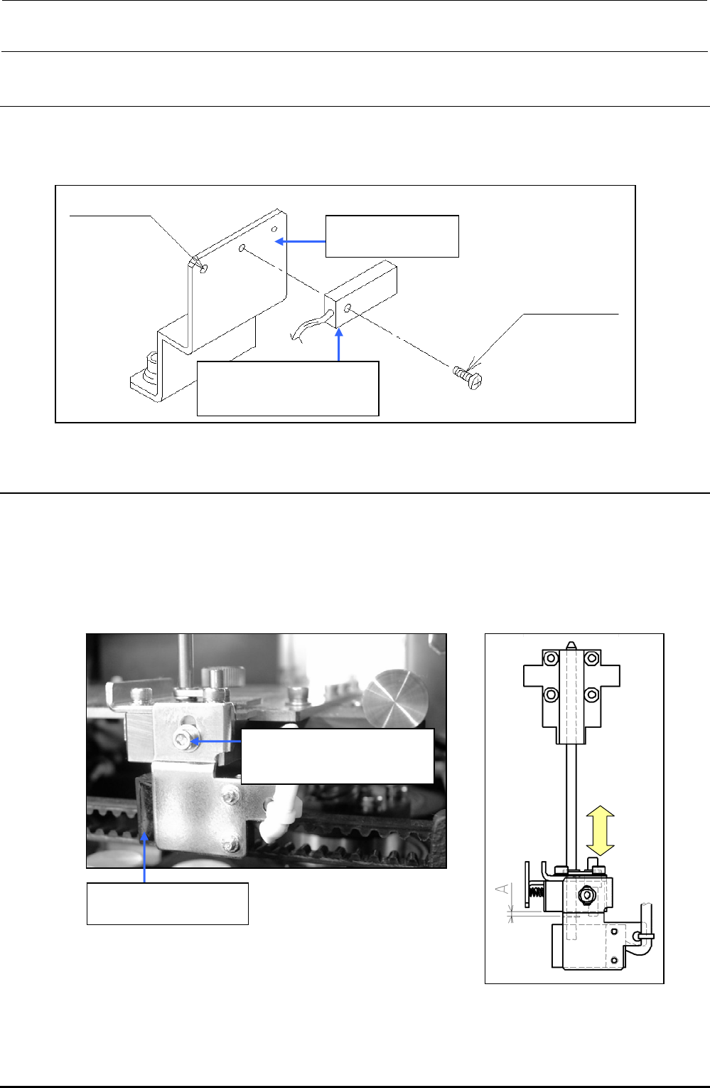
5-7. Replacing the Support Table Home Position Sensor
(BU Home Position Sensor)
1) Detach the sensor from the sensor bracket.
2) Adjust the distance between the sensor and sensor dog to 1 mm.
Figure 5-7-1 BU Home Position Sensor
5-8. Replacing the T-PIN Sensor (Optional)
1) Remove the adjustment screw to detach the sensor bracket and replace the sensor.
When reassembling the components, adjust the position of the sensor bracket by loosening the
adjustment screw and moving the sensor bracket up and down so that the T-PIN sensor is
turned ON when the center ring pin is lowered by 1.5
0
-0.5
mm.
2) Carefully handle the cables.
Figure 5-8-1 T-PIN Sensor
40046962
BU sensor bracket
40002124
Backup table home
position sensor assembly
For tie-band
Screw supplied
with sensor
SL6030692TN
SEMS cap bolt with washer
M3×6
40002122
T-PIN sensor assembly
FX-3R Maintenance Guide
5-12
Rev. 1.00
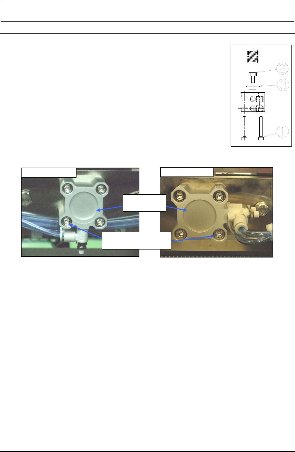
5-9. Replacing the Pusher Y Cylinder (Outer Shape Reference)
1) Remove the parts c to detach the cylinder. As the cylinder is detached,
the spring is also then removed.
2) Detach the speed controller from the cylinder. (At this time, check what
side the speed controller has been mounted.)
3) With the cylinder rod secured with a spanner, remove the part d with
another spanner.
4) Reassemble the components in the order of steps 3) to 1).
5) After the cylinder components have been assembled, supply the air
(0.49 MPa) to check that the cylinder moves smoothly.
∗ The cylinder mounting direction of the front reference machine is different from that of the rear
reference machine.
∗ For the rear reference machine, secure the speed controller with a tie-up band so that it does not
interfere with the width adjustment timing belt when the PWB width is set at its maximum level.
∗ The speed controller of the cylinder has been adjusted (page 5-9 in QA Table). No adjustment is
needed even after replacement of the parts.
Figure 5-9-1
Pusher Y-Cylinder
[Front reference] [Rear reference]
PA250100100
Cylinder
SM6053502TN
SEMS cap bolt M5×35
Figure 5-9-2
Pusher Y-Cylinder (Front Reference)
Figure 5-9-3
Pusher Y-Cylinder (Rear Reference)
FX-3R Maintenance Guide
5-13
Rev. 1.00
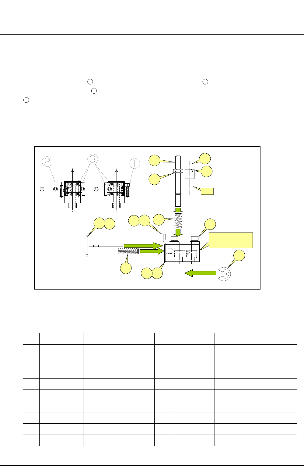
5-10. Replacing the Centering Pin (Optional)
1) Loosen the screws c, d and e of the guide block A and guide block B to detach the centering
pin together with the guide blocks.
2) At this time, also detach the T-PIN sensor (together with its bracket) from the reference side.
Removing the E ring
12
allows you to pull the centering pin
17
from the damper block.
Removing the E rings
16
(two in total, top and bottom) allows you to remove the centering pin
17
.
When installing a new centering pin, reassemble the components in the reverse order. The
E-rings must also be replaced with new ones.
After the components have been reassembled, adjust the sensor position in the same manner
as described in 5-10, Replacing the T-PIN Sensor.
Figure 5-10-1 Centering Pin
Table 5-10-1 Reference for PWB Positioning Hole
[List of Replacement Parts]
Part No. Part name
Part No. Part name
1 40000886 GUIDE_BLOCK_ASM 10
40000895 DAMPER_BLOCK_R
2 40000887 GUIDE_BLOCK_A_ASM 11
SL6030892TN SCREW
3 40000889 GUIDE_BLOCK_B_ASM 12
RE0300000K0 E-RING
4 40000891 STOPER_SLIDE_LEVER_L 13
40000896 DAMPER_LOCK_PIN
5 40000897 STOPER_SLIDE_LEVER_R
14
40000978 DAMPER_LOCK_LINK
6 40000892 DAMPER_BLOCK_L 15
40000950 DAMPER_SPRING
7 40015791 DAMPER_PLATE_L 16
RE0300000K0 E-RING
8 40015792 DAMPER_PLATE_R 17
40001081 CENTERING_PIN 4.0
9 40015793 LOCK_SPRING
⑦
④
⑰
⑬
⑭
⑯
A
⑤
⑨
⑮
⑧
⑪
B部
右側=⑧+⑩+⑪
左側=⑦+⑥+⑪
⑫
⑩⑥
Section B
Right side = ⑧+⑩+⑪
Left side = ⑦+⑥+⑪