JUKI FX-3R MAINTENANCE GUIDE.pdf - 第70页
FX-3R Maintenance Guide 5-17 Rev. 1.00 5-12. Replacing the Support Table ENC 1) Detach the support table in the same manner as described in 5-11, Replacing the su pport table Motor. 2) Loosen the screw d , and move the t…
FX-3R Maintenance Guide
5-16
Rev. 1.00
<Adjustment Procedure>
1) Select [Manual Control] → [Transport Control] to set the support table to a position of −27mm.
2) Based on the lowest point of four measured points, turn the adjustment screw in the down
direction (screw tightening direction) to make the adjustment so that the difference among four
measured points is 0.02mm or less.
∗ If all of three screws (screws around the adjustment screws) fixing the ball screw are loosened,
the table may be lowered. To prevent such trouble, always tighten the screws temporarily after
the adjustment with the adjustment screws has been completed.
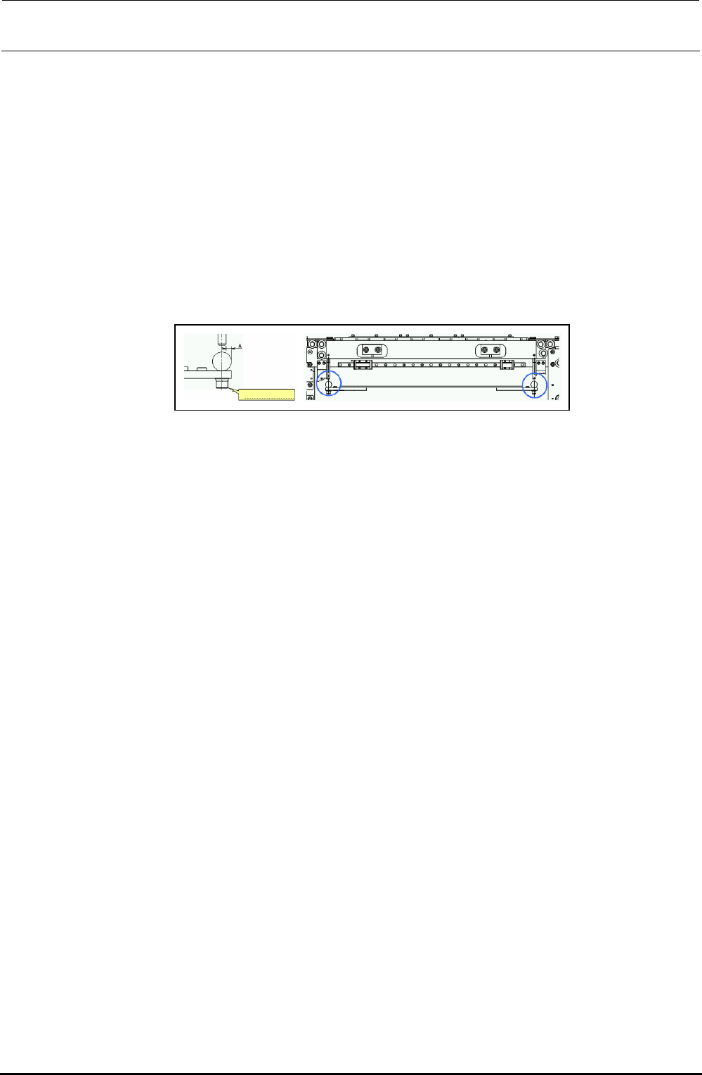
∗ After the adjustment has been completed, make sure that the center of the rail guide shaft is
aligned with that of the side beam.
(A-dimension is 4mm±1mm.)
Figure 5-11-3-2 Rail Guide Shaft and Side Beam
Side beam setscrew
FX-3R Maintenance Guide
5-17
Rev. 1.00
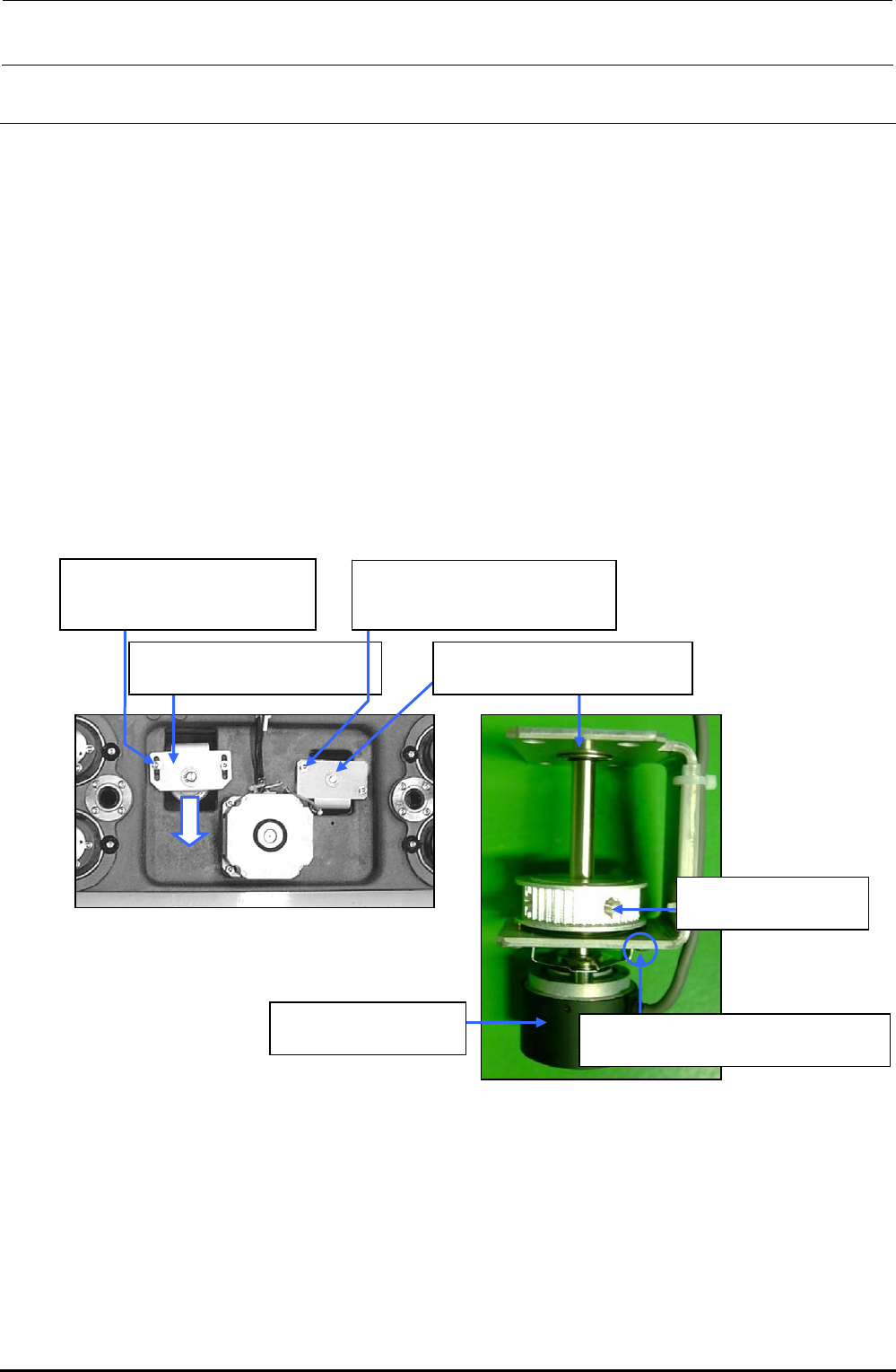
5-12. Replacing the Support Table ENC
1) Detach the support table in the same manner as described in 5-11, Replacing the support table
Motor.
2) Loosen the screw d, and move the tension support assembly c in the arrow direction to
loosen the tension of the timing belt
3) Loosen the screw f to detach the encoder bracket assembly e.
4) Loosen the screw supplied with the encoder (hollow set screw h) and fixing screw i to detach
the BU ENC assembly g.
5) When installing a new BU ENC, reassemble the components in the order of steps 4) to 1).
Adjust the flatness of the support table as described in 5-11 “Replacing the Support Table
Motor.”
After the components have been reassembled, obtain the support table offset from MS
parameters.
d SL6051492TN
SEMS cap bolt with washer
M5×14
c 40000937
Tension support assembly
f SL6051492TN
SEMS cap bolt with washer
M5×14
g E94337290A0
BU ENC Assembly
h SM8040802TP
Set screw M4×8
e 40000934
Encoder bracket assembly
i SL6030692TN
SEMS cap bolt with washer M3×6
Figure 5-12-2 BU ENC Assembly
Figure 5-12-1 Conveyor Base Assembly (L)
FX-3R Maintenance Guide
5-18
Rev. 1.00
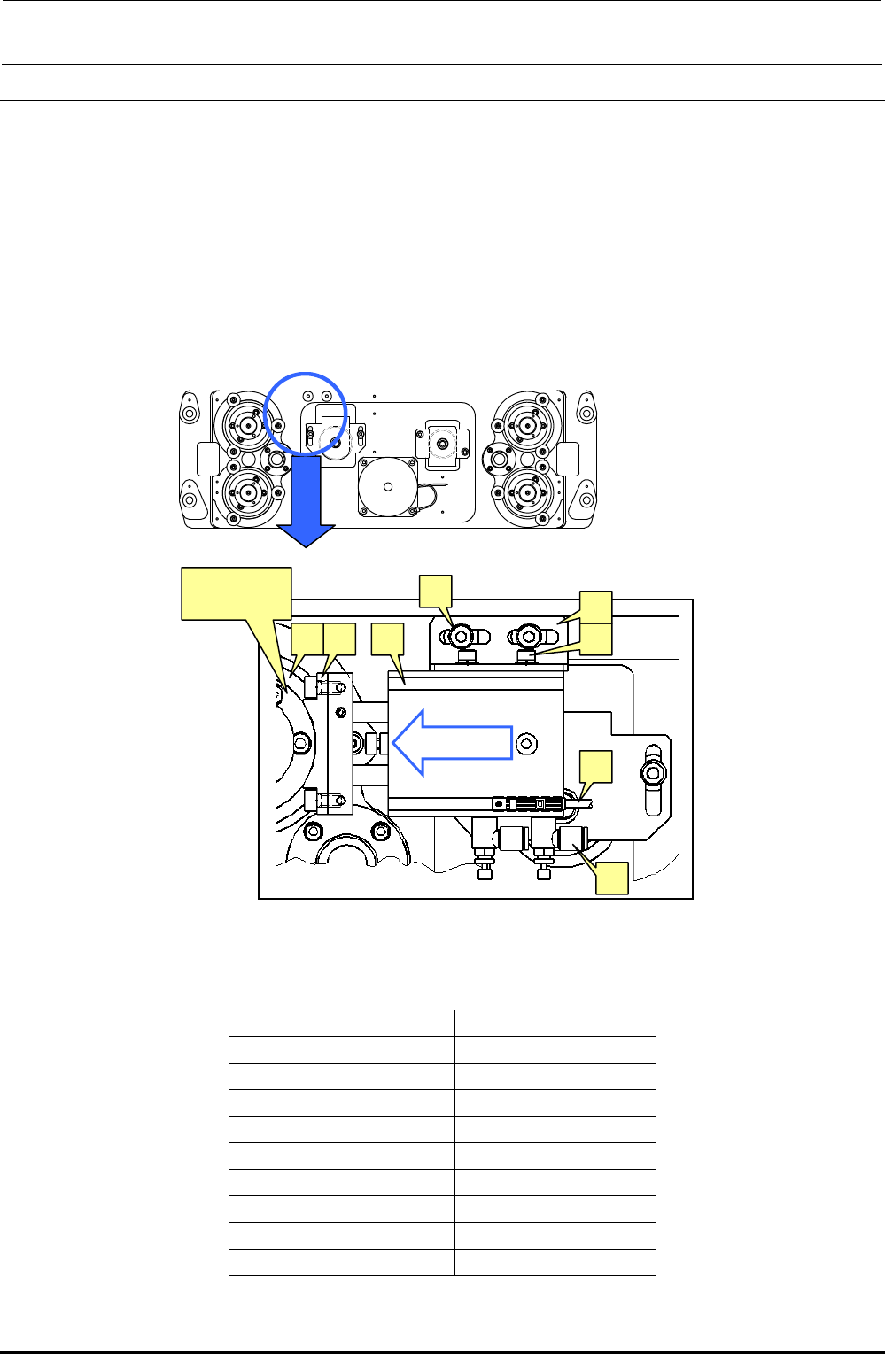
5-13. Replacing the Backup Stopper (for EN Type Only)
1) Loosen the BU stopper bracket set screw h with the air turned ON to adjust the crosswise
position of the BU stopper. Loosen the air cylinder set screw f and make the adjustment so
that the height of the BU stopper (rubber part) c is matched with the height of the flange outer
periphery of the ball screw. After that, check that the dimension A shown in the right portion of
Figure 5-8-1 is 5 mm.
2) For the lock sensor position of the BU stopper, loosen the BU lock sensor set screw k, move
the sensor from the cylinder retract status in the B direction. After the sensor has been turned
ON (LED goes off), further move the sensor 1 mm and secure it firmly.
3) To adjust the speed controller, loosen the lock nut of the speed controller j, turn the speed
controller 3 rotations from its fully closed position, and then secure it with the lock nut.
Figure 5-13-1 Backup Stopper
[List of Replacement Parts]
Table 5-13-1 Replacement Parts of Backup Stopper (Reference for PWB Positioning Hole)
Part No. Part name
c
40000970 BU_STOPER
d
SM6051002TN SCREW
e
PA150101100 DUAL_AIR_CYRINDER
f
SL6040892TN SCREW
g
40000971 BU_STOPER_BRACKET
h
SL6051492TN SCREW
i
BT0400251EA AIR_TABE
j
PC010508000 SPEED_CONTROLLER
k
40002241 BU_LOCK_CABLE_ASM
cd e f
g
h
j
k
Ball screw
flange
“B” direction