JUKI FX-3R MAINTENANCE GUIDE.pdf - 第78页
FX-3R Maintenance Guide 5-25 Rev. 1.00 3) Disconnect the BARCODE READER relay connector. (The relay connector is con nected to the relay cable at a position close to that shown in the Figure below.) The black line shows …
FX-3R Maintenance Guide
5-24
Rev. 1.00
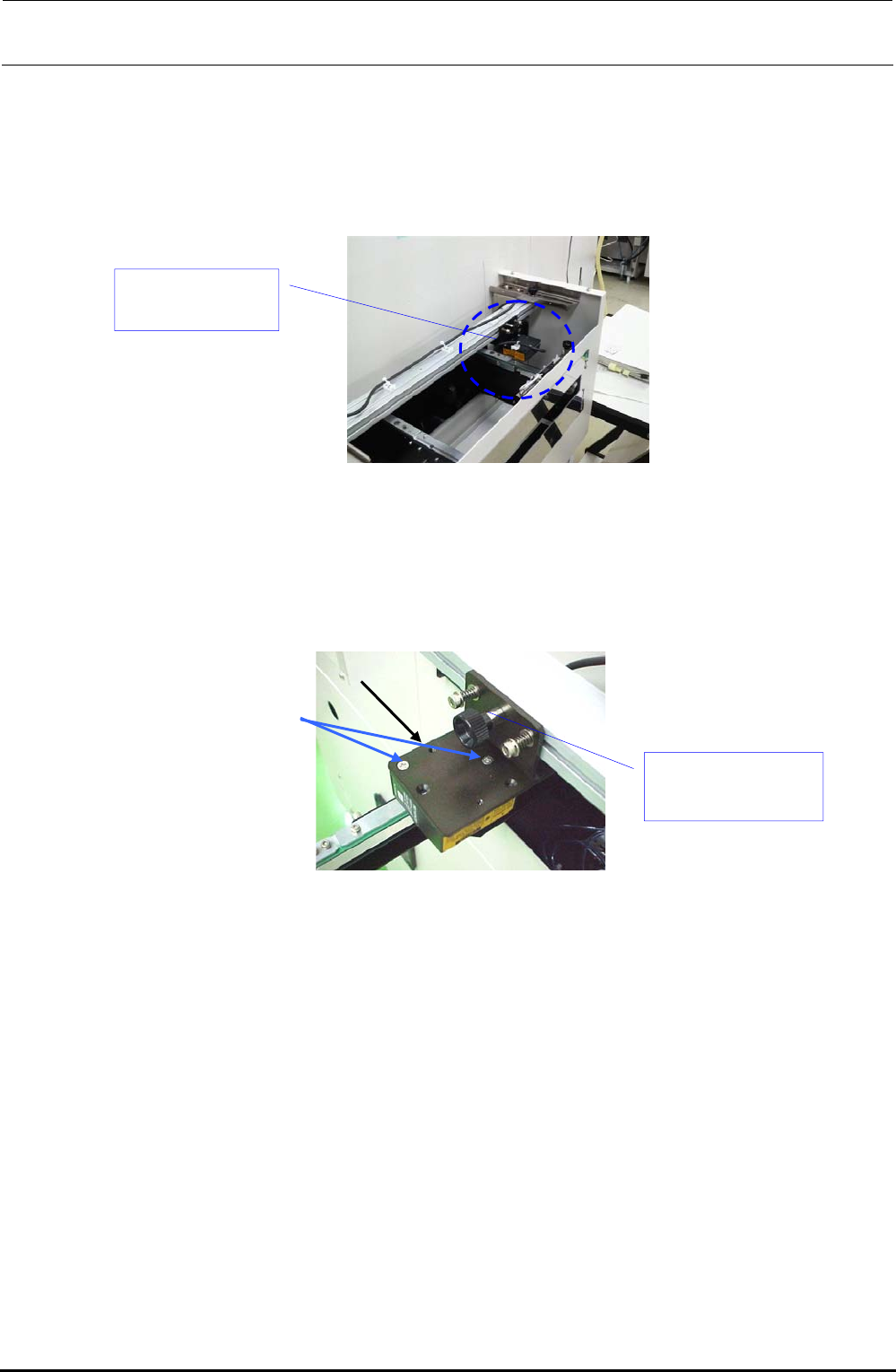
(3) Replacement procedure
The barcode reader (HX006100000) has been assembled to the PWB transport inlet as shown in
the Figure below.
(This Figure shows the left → right transport machine. For the right → left transport machine,
the barcode reader is assembled to a position opposite to that shown in this Figure.)
Figure 5-15-1
1) Remove the flat head screws e (2 pcs.) to detach the BARCODE READER d from the
ROTARY PLATE c.
Figure 5-15-2
2) Cut the tie-up band bundling the barcode reader cables.
Barcode reader
(HX006100000)
e
c
d Barcode reader
(HX006100000)
FX-3R Maintenance Guide
5-25
Rev. 1.00
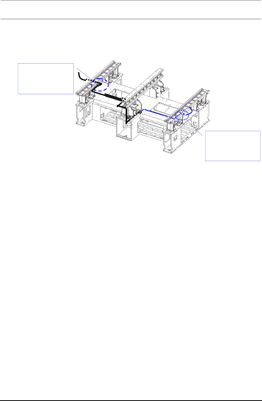
3) Disconnect the BARCODE READER relay connector. (The relay connector is connected to
the relay cable at a position close to that shown in the Figure below.)
The black line shows the cable route for the left → right transport while the blue line shows
that for the right → left transport.
Figure 5-15-3
4) Mount a new BARCODE READER with the flat head screws e while referring to its
orientation.
Connect the relay connector. Bundle the cables, and then run them through the original route.
Relay connector
connection position
(For left → right
transport)
Relay connector
connection position
(For right → left
transport)
FX-3R Maintenance Guide
6-1
DANGER
To prevent any trouble caused by accidental machine start, always
shut-down the power before starting the maintenance and
adjustment work.
[6] CAL BLOCK
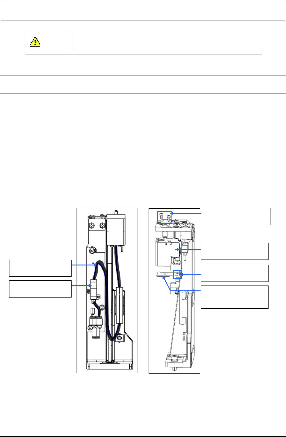
6-1. Replacing the CAL Board Assembly
(1) Disconnect the cables from the CAL board.
(2) Disconnect the φ4-air tube c from the air suction filter d.
(3) Remove the M3 cap bolts e (two locations) to detach the CAL side cover f.
∗ At this time, do not loosen any flat countersunk head screw, but remove only the M3-cap
bolt.
(4) Remove the M3 SEMS cap bolts g (two locations) to detach the board h from the CAL side
cover f and φ4-air tube c.
The CAL board assembly h can then be taken out.
(5) After the board has been replaced, reassemble the parts and components in the reverse order
of disassembly.
c BT0400251EB
φ4-air tube (black)
d PF0100030A0
Air suction filter
e SM6030602TN
SEMS cap bolt M3×6
f L202E521000
CAL side cover
g SL4030691SC
SEMS cap bolt M3×6
h 40007376
CALBLOCK board
assembly
Figure 6-1-1 Side View Figure 6-1-2 Front View
It is possible to replace the filter element inside the air suction filter d without shutting down of the
air supply.
Part No. PF901009000, Part name FILTER ELEMENT
Rev. 1.00