JUKI FX-3R MAINTENANCE GUIDE.pdf - 第84页
FX-3R Maintenance Guide 8-2 8-1-2. Adjusting the Speed Cont roller of the Bank-Up Cylinder (Optional Replacement Table) 1) For the speed controllers of the right side cylinder, adjust those of the fixed and left side cyl…
FX-3R Maintenance Guide
DANGER
To prevent any trouble caused by accidental machine start, always
shut-down the power before starting the maintenance and
adjustment work.
[8] FEEDER BANK, REPLACEMENT TABLE AND ELECTRIC BANK
(OPTIONAL)
8-1. Common Parts and Units for Mechanical Feeder and Electric Feeder
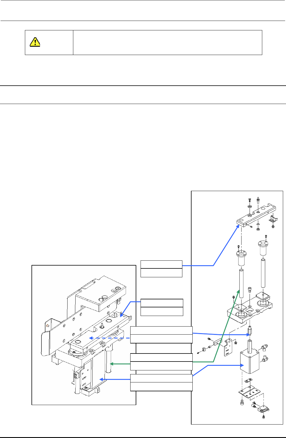
8-1-1. Replacing the Bank-Up Cylinder
1) Turn off the power to the main unit.
2) Turn on the selector switch, and the left and right roller levers to raise the bank lifter.
3) Loosen the lifter cylinder shaft to detach the bank-up cylinder (cylinder to be replaced).
4) Shut-down the main compressed air to the main unit (with the hand valve).
5) Remove the lifter supporter assembly mounting screws.
6) Pull out the bank lifter upward. (Bank lifter to be replaced)
7) Remove four bank-up cylinder mounting screws to detach the cylinder.
8) Mount the speed controller on a new cylinder.
9) Mount the cylinder and insert the bank lifter from the top.
10) Screw the lifter cylinder shaft into the cylinder rod.
11) Mount the lifter supporter.
12) Supply the main compressed air to the main unit.
13) Adjust the speed controllers of the left and right cylinders.
(Section 8-6.)
14) Mount the replacement table on the main unit.
15) Turn on the power.
8-1
Rev. 1.00
40047264
Bank lifter RS
40047265
Bank lifter LS
40047263
Lifter cylinder shaft 85
40047261
Lifter guide shaft 25
PA630850100
Air cylinder
Figure 8-1-1-1 Back-Up Cylinder Related Parts
Figure 8-1-1-2 Lifter Supporter
FX-3R Maintenance Guide
8-2
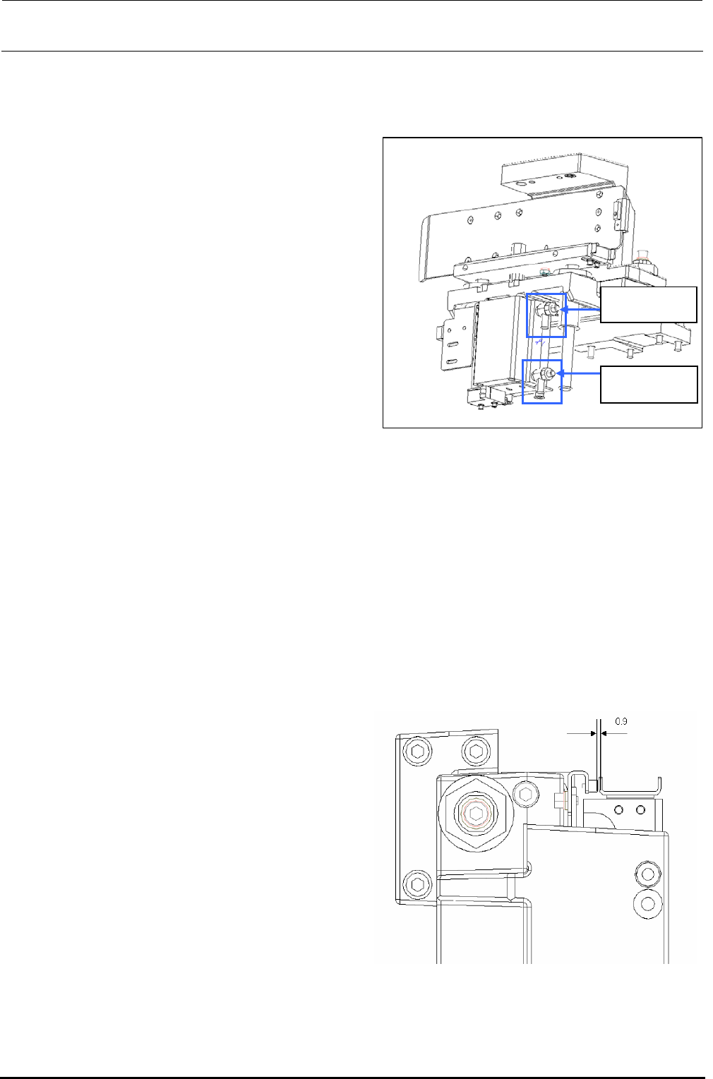
8-1-2. Adjusting the Speed Controller of the Bank-Up Cylinder
(Optional Replacement Table)
1) For the speed controllers of the right side
cylinder, adjust those of the fixed and left side
cylinders.
2) The speed controllers have been set so that
the bank-up cylinder completes ascent
operation in 3.8 to 4.2 seconds, descent
operation in 2 to 2.5 seconds. (When
assembled)
• UP speed : To be adjusted by the
upper speed controller.
Upper speed
controller
Lower speed
controller
Figure 8-1-2-1 Back-Up Cylinder
Positions
If the up speed of the left cylinder is too fast,
turn the speed controller adjustment screw
clockwise.
• DOWN speed: To be adjusted by the lower
speed controller.
If the down speed of the left cylinder is too
fast, turn the speed controller adjustment
screw clockwise.
3) If the up and down speeds of the left and right cylinders are the same, lock the adjustment
screws of the speed controllers with the lock screws.
4) After the adjustment screws have been locked, recheck the up and down speeds.
8-1-3. Replacing the Bank-Up Detection Sensor
(Optional Replacement Table)
1) Turn off the power to the main unit.
2) Lower the lifter.
3) Loosen the fixing screws, remove the sensor
and replace it with a new one.
4) Reassemble the components in the reverse
order of disassembly.
<Adjustment>
1) Turn on the power to the main unit.
2) Make sure that there is a 0.9mm gap
between the bank sensor dog and sensor
as shown on the right.
Figure 8-1-3-1 Back-Up Detection Sensor
Rev. 1.00
FX-3R Maintenance Guide
8-3
Rev. 1.00
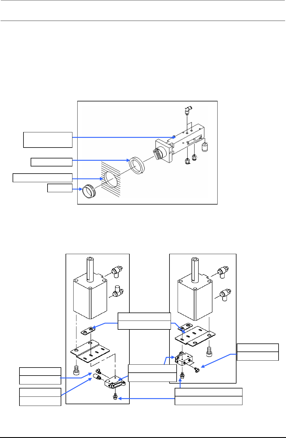
8-1-4. Replacing the Selector Switch (Optional Replacement Table)
1) Shut-down the main compressed air to the main unit (with the hand valve).
2) Turn the selector switch cap counterclockwise to detach the selector switch from the cover.
3) Mount the half-union and silencer on a new selector switch and secure the selector switch to
the cover with the cap.
4) Supply the main compressed air to the main unit.
Figure 8-1-4-1 Selector Switch Assembly (40000585)
8-1-5. Replacing the Roller Lever (Optional Replacement Table)
Before replacing the roller lever, always shut-down the main compressed air.
Cap
Cover mounting hole
Rubber, 3 pcs.
PV0151170A0
Selector switch
PJ304040505
Elbow union
E2811729000
Valve nut plate
PV010505000
Mechanical valve
PJ304040505
Elbow union
PX050501000
Silencer
Roller lever assembly
with silencer
Roller lever assembly
with elbows at both ends
SL6042592TN
SEMS cap bolt M4×25
Figure 8-1-5-1 Roller Lever