JUKI FX-3R MAINTENANCE GUIDE.pdf - 第93页
FX-3R Maintenance Guide 8-11 8-2-5. Replacing the Bank PCB 1) Remo ve the mounting screws to det ach the front panel. 2) Disconnect the connectors (cables) from the mechanical bank PCB. 3) Remo ve the round head screws (…
FX-3R Maintenance Guide
8-10
8-2-3. Adjusting the Speed Controller of the Drive Cylinder
The following describes how to adjust the up speed of the
drive cylinder.
Rev. 1.00
1) Detach the drive cylinders to be adjusted from the
driver bracket.
2) Connect the air tube and connector.
3) Supply the main compressed air and turn on the
power.
4) Using the manual control, operate all drive cylinders
continuously, the speed controller of which needs to
be adjusted.
5) Adjust the speed controller of the cylinder to be
adjusted visually so that the movement of the cylinder
is the same as that of other cylinders.
6) Tighten the nut of the speed controller firmly. After the
nut has been secured, recheck that the cylinder
functions correctly.
Figure 8-2-3-1 Speed Controller of
Drive Cylinder
Speed controller
7) Reassemble the components in the reverse order of
disassembly.
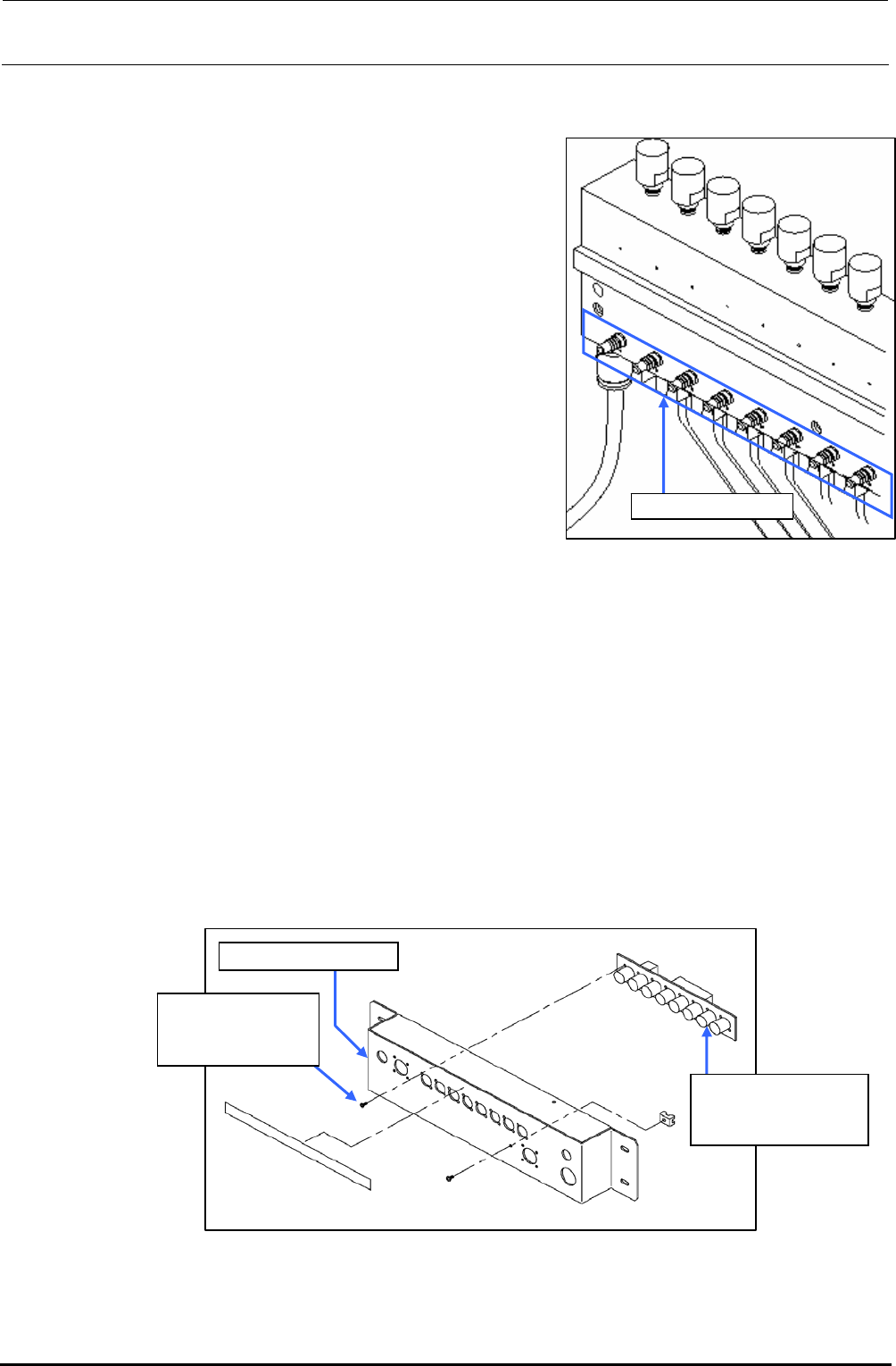
8-2-4. Replacing the Feeder Bank Board (Optional)
1) Disconnect the connector bracket IF cable, connector bracket PWR cable.
2) Remove the mounting screws to detach the connector bracket.
3) Disconnect the connectors from the feeder bank board.
4) To detach the feeder bank board, remove eight round head screws. After relevant board has
been detached, replace it with a new one.
5) Reassemble the components in the reverse order of disassembly.
Connector bracket
E86157150A0
Feeder bank board
assembly
SM4860601SC
Round head screw
M2.6×6
Figure 8-2-4-1 Feeder Bank Board Related Part Names
FX-3R Maintenance Guide
8-11
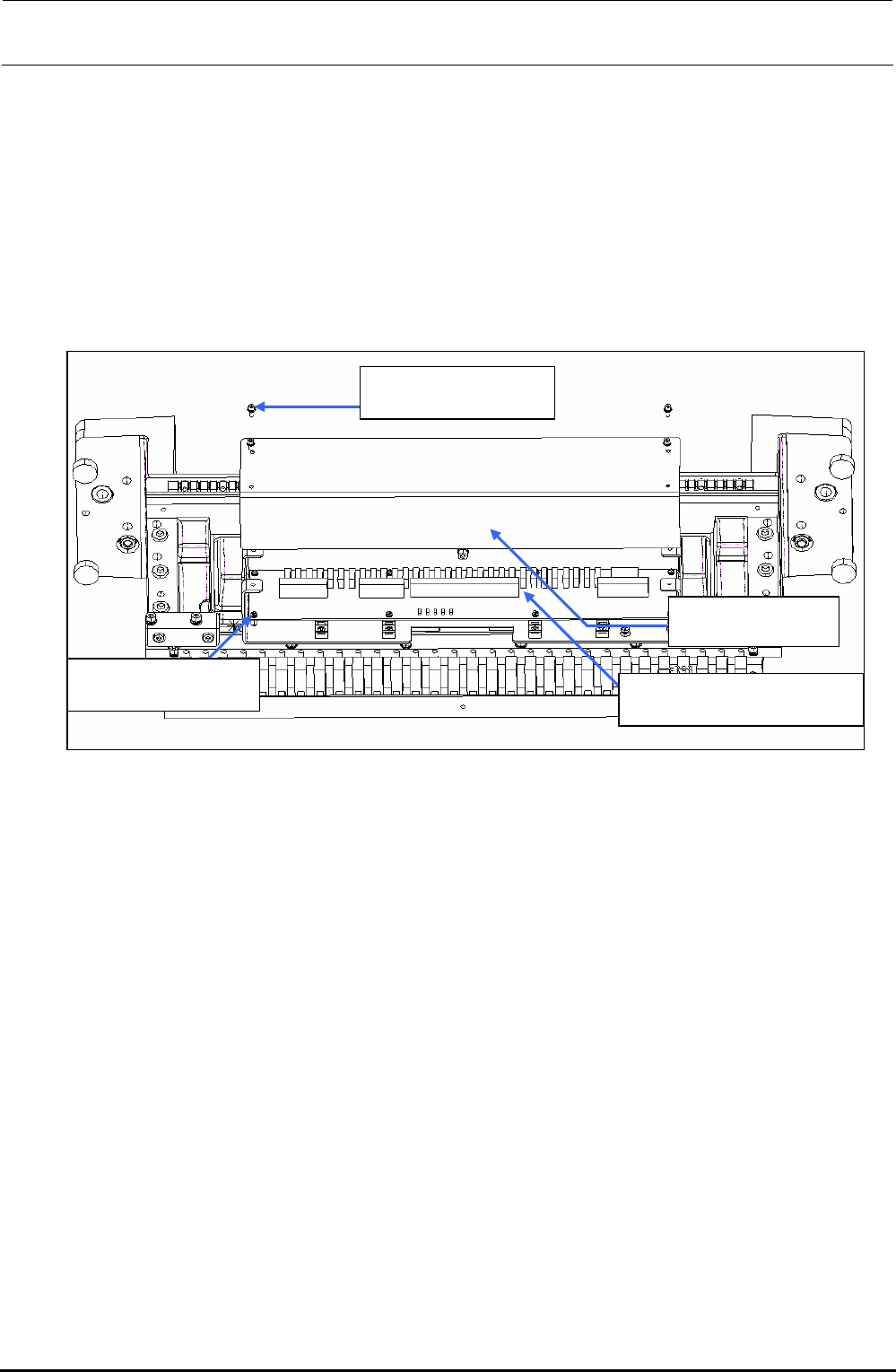
8-2-5. Replacing the Bank PCB
1) Remove the mounting screws to detach the front panel.
2) Disconnect the connectors (cables) from the mechanical bank PCB.
3) Remove the round head screws (8 pcs.) to detach the mechanical bank PCB and replace it with
a new one.
4) Reassemble the components in the reverse order of disassembly.
SL6030692TN
SEMS cap bolt M3×6
40047311
Front panel
40082808
Mechanical bank PCB ASM
SL4030681SC
SEMS cap bolt M3×6
Figure 8-2-5-1 Bank PCB (When Viewed Slantwise from the Lower Portion)
Rev. 1.00
FX-3R Maintenance Guide
8-12
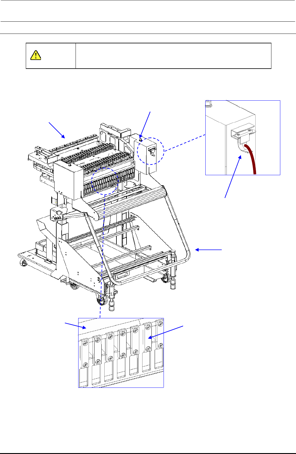
8-3. Replacement Table for Electric Feeder
DANGER
To prevent any trouble caused by accidental machine start, always
shut-down the power before starting the maintenance and
adjustment work.
8-3-1. Overall Drawing (Replacement Table for ETF)
40084841
EF setup cable 1 bracket
assembly
40084666
E_Trolley cover R
40084636
FDC bracket
40084831 - EF IF CBL 26-30 ASM
40084829 - EF IF CBL 16-20 ASM
40084830 - EF IF CBL 21-25 ASM
40084827 - EF IF CBL 6-10 ASM
40084828 - EF IF CBL 11-15 ASM
40084826 - EF IF CBL 1-5 ASM
40084912
ETF trolley assembly
40084911
ETF bank assembly
Figure 8-3-1-1 Overall Drawing
Rev. 1.00