DT_ELMC-V3-EN_REV-B.1_L.pdf - 第9页
ELECTROVA P ® E LMC 9 2.4 IMPORTANT INSTRUCTION S • Ambient temperature: between 5 and 40°C • Ambient humidit y: < 80 % Rel ative humid i ty • Back side: this component heats during operation (up to 60°C). Make sure t…
ELECTROVAP® ELMC
8
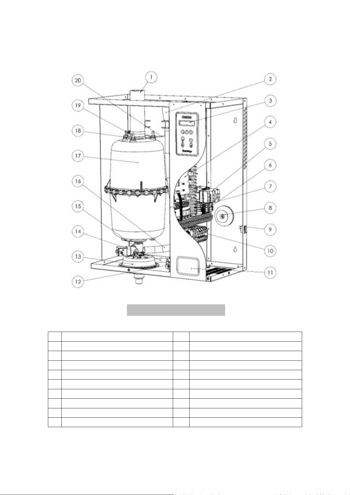
2.3 HUMIDIFIER COMPONENT PARTS
1
Steam hose
11
Identification label
2
Filling cup
12
Water inlet valve
3
LCD display board
13
Funnel
4
Main circuit board
14
Overflow hose
5
Power contactor
15
Drain valve
6
Fuse holders
16
Filling hose
7
3 relay board (optional)
17
Steam Cylinder
8
Transformer
18
High water level electrode
9
ON/ OFF Switch
19
Power electrode
10
Power rail
20
Cylinder retaining clip
Fig. 2-3. Humidifier component parts
ELECTROVAP® ELMC
9
2.4 IMPORTANT INSTRUCTIONS
• Ambient temperature: between 5 and 40°C
• Ambient humidity: < 80% Relative humidity
• Back side: this component heats during operation (up to 60°C). Make sure that the support of the device is
not made of a heat-sensitive material.
• Wall mounting: Please be careful that the support material receiving the device (pillar, wall, etc.) can support
it.
• Fixation: use a fastening system adapted to the support material.
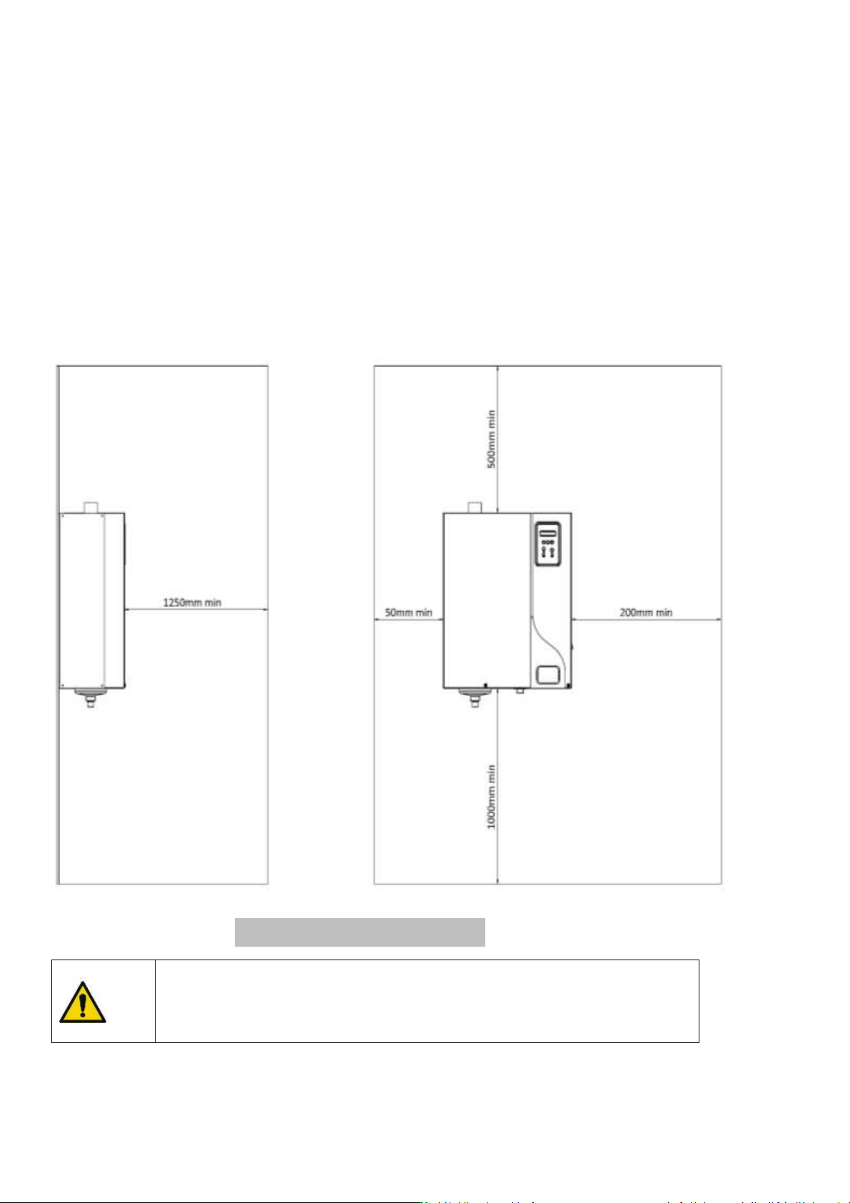
• Make sure that the mounting distances are met.
Please read and follow the enclosed safety information and the warning labels
inside the humidifier before installation or maintenance.
Some steps can be dangerous.
Visit our website or contact our operators for technical support.
Fig.2-4. Mounting distances
ELECTROVAP® ELMC
10
3. INSTALLATION
3.1 PROCEDURE
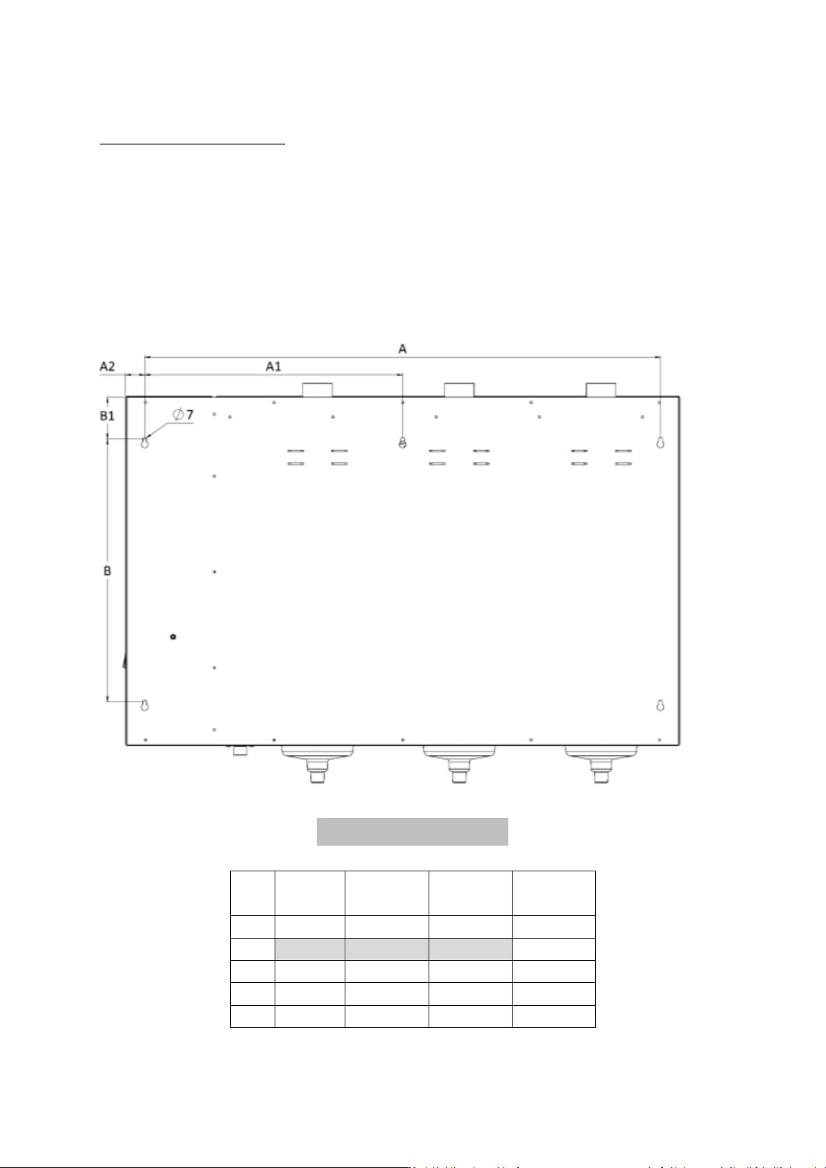
• Mark and drill where indicated (holes size depends on the selected dowels and support materials).
• Put the dowels in the holes.
• Screw the top screws into the dowels (M6 recommended), let them protrude by about 10 mm/0.39in.
• Hang the device to the top screws and align it vertically and horizontally with a bubble level.
• Tighten up all screws.
(*)
SC = Small Cylinder - MC= Medium Cylinder
ELMC
1 SC
(*)
ELMC
1 MC
(*)
ELMC
2 MC
(*)
ELMC
3 MC
(*)
Has:
400
450
750
1000
A1:
500
A2:
35
53
23
38
B:
400
510
510
510
B1:
81
81
81
81
Fig. 3-1. Installation holes