KE2010.Instruction Manual.Ver.2.01,Rev.08.pdf - 第1063页
258 C. Detailed Explanations of VCS Er rors 1. Detailed Explanations of VCS Errors Displayed on the VCS Monitor If the system fails to r ecognize a mar k or com ponent, a recognition er ror detailed code appears on the m…
257
[Treatment] “YES” button will save the set value. “NO” button will not save it. “Cancel” button
will cancel the inquiry.
Q907011 “Return to home has not yet been completed. Return to home?”
[Cause] The axis has not yet been returned to home. You are asked if you want to
perform the Home returning of the axis?
[Treatment] “YES” button will return the axis to home, and continue the process. “NO” button
will not return the axis to home, and continue the process.
Q907021 “Cannot return component. Trash component?”
[Cause] A component was detected in the Component presence checking that is
performed when returning nozzle to ATC. The component can not be returned
since its pick position is unknown. You are asked if the component can be
disposed.
[Treatment] “YES” button will dispose the component at a disposal position. “NO” button will
move the head to the waiting position for nozzle removal, and request for a
component removal.
I908001 “Remove the component from %s”
[Cause] The nozzle can not be returned to ATC since something, such as a component, is
attached to the nozzle.
[Treatment] ?Please remove the component from the head manually.
I909001 “Nozzle is removed from %s to ATC”
[Cause] A nozzle has still been on the ? head.
[Treatment] “OK” button will check the component presence, and return the nozzle making
sure that no components on it.
I909002 “Calibration jig for laser alignment will be returned to jig station”
[Cause] The jig of ? is on the Calibration block or is being picked up.
[Treatment] “OK” button will return the jig to the jig station.
258
C. Detailed Explanations of VCS Errors
1. Detailed Explanations of VCS Errors Displayed on the VCS Monitor
If the system fails to recognize a mark or component, a recognition error detailed code appears
on the monitor. This detailed code is an ASCII character string, and is separated with a space
(blank character), underscore“_”, and/or return mark. The number of marks/components
recognized at the same time and their phase number are normally fixed to “1”. However, if a
KE-2030 recognizes two or more marks at a time or a KE-2040 recognizes two or more
components at a time, the number of marks/components recognized at the same time is set to
“2”, and the phase number is set to “1” (for a mark or component recognized first) or 2 (for a
mark or component recognized the next).
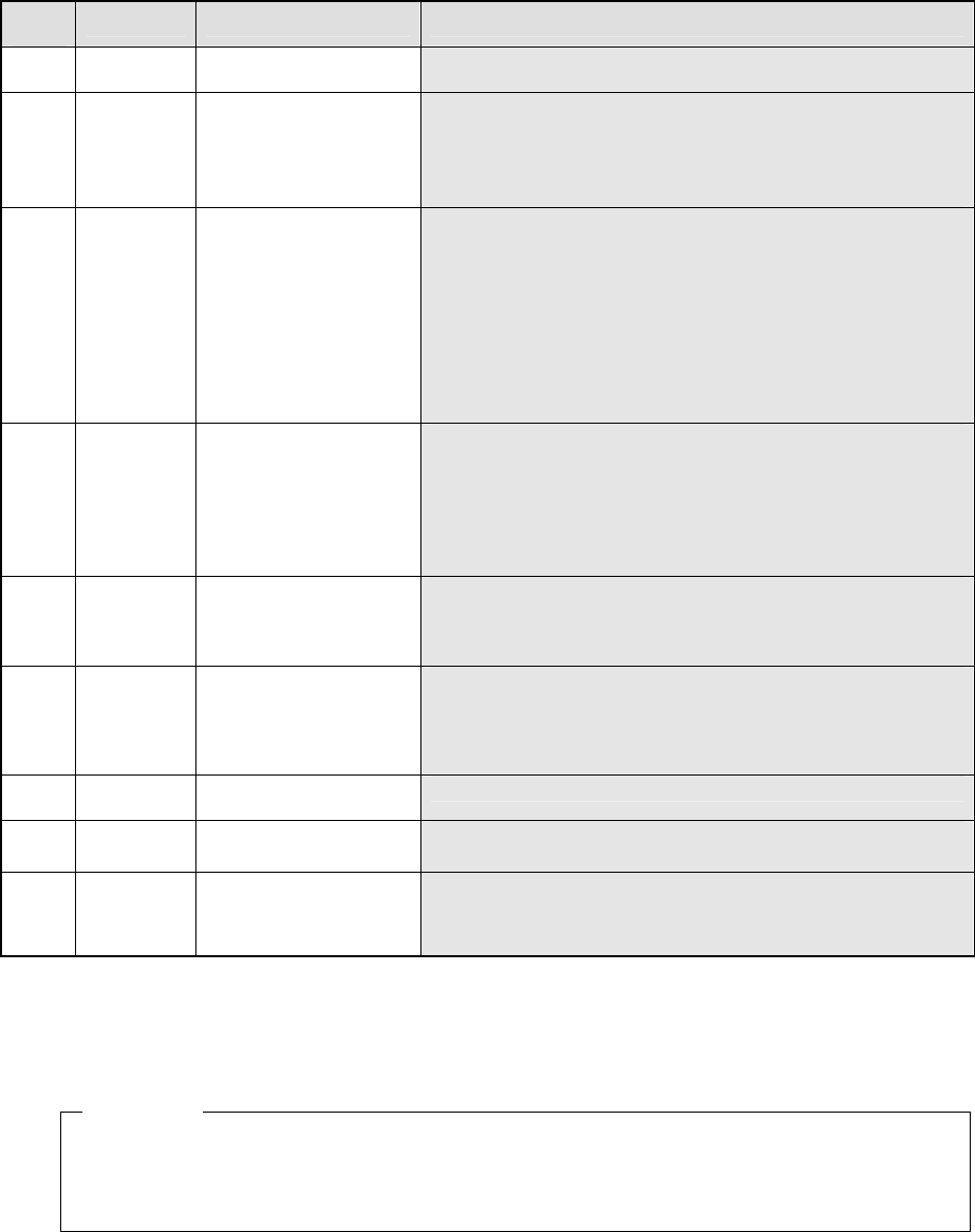
2. Detailed Explanations of Mark Recognition Errors
‘RES M N Type Index ErrCode …..’
M: Number of marks recognized at the same time
N: Phase number for simultaneous mark recognition
Type: Mark type (BO: Board mark ICM: IC mark SAC: Bank mark)
Index: Mark identification number
Err
Code
.............. Description of an error Assumed cause
1 There is no mark. − This error occurs when the system recognizes a mark at a place
where a mark should not exist.
− This error occurs also when the light does not turn on.
2 A mark is in contact with
the detection frame.
− This error occurs when a mark is in contact with the mark
detection area.
4 Corr The mark similarity is too
low.
− This error occurs when a mark is extremely stained.
5 The VCS internal error
such as a hardware error
occurs.
− This error occurs when the VCS hardware malfunctions.
Corr: Similarity detected as an error (0 to 999)
The detailed information on a recognition error derived from the user definition template is
structured in the same way as those derived from a mark.
RES 1 1 B0 0 2
This error means that a BOC mark whose ID is “0” is in contact with the detection frame.
Example
259
3. Detailed Explanation of the Recognition Errors of Standard Lead
Components
‘RES M N Type Index ErrCode …..’
M: Number of components recognized at the same time
N: Phase number for simultaneous component recognition
Type: Component type
QFP, SOP, PLCC, SCTI, SCTB, SCTO, CON, CON2, SOJ, ZCON,
HSOP, SODIMM
Index: Component identification number
Err
Code
.............. Description of an error Assumed cause
1 Side Pos
Bend
A lead is bent. − A lead is damaged and bent.
2 Side Num The number of leads is
smaller than that
regulated.
− The number of leads you specified is larger than that of the leads
actually located on a component.
− A certain lead(s) cannot be detected normally due to its (their)
stains.
− Since a lead is not glossy at all, it cannot be detected normally.
3 Side Pos The length of some leads
is abnormal.
− This error occurs because one lead is bent, and the position of
its tip is not aligned with that of other leads.
− There are substances similar with a lead such as metal fittings
(connector) on both ends of a lead. When such substances
cannot be removed, this error occurs.
− There are substances similar with a lead such as metal fittings
(connector) on the body. When such substances cannot be
removed, this error occurs
− A scratch or stains of a nozzle reflects light to a tip of a lead, so
the lead is displayed as if its length becomes longer.
4 Side No lead can be detected. − This error occurs when the lead detecting window cannot be set
normally due to the stained VCS.
− Vision data is not set correctly (the lead pitch you set is quite
different from the actual pitch.)
− The displayed lead is too short. (This error occurs more
frequently if the displayed lead is 0.3 mm or shorter on the
standard view of display.)
5 Side Num There are only a few
leads on a component.
− This error occurs when almost all leads cannot be detected
normally due to their stains.
− This error occurs also when almost all leads are unglossy, so
cannot be detected correctly.
6 Side Num There are too many
leads on a component.
− The number of leads you set is smaller than that of leads actually
located on a component.
− There are substances similar with a lead such as metal fittings
(connector) on both ends of a lead. When these substances
cannot be removed, this error occurs.
7 Side The lead pitch is
abnormal.
− Vision data (lead pitch) is not set correctly.
8 There is no component. − A component is not picked correctly.
− This error occurs also when the light does not turn on.
9 Side Num There are not enough
leads on a component.
− This error occurs when leads of a 0.4-mm-pitch lead component
are not glossy on the standard view of display or when leads of a
0.3-mm-pitch lead component are not glossy on the option-1
view of display.
Side: Side at which the system detected an error
(0: top side, 1: bottom side, 2: left side, 3: right side)
Pos: The lead number on which the system detected an error (from 1)
Num: The number of leads that were detected
Bend: The lead-bending ratio to the lead pitch (%)
RES 1 1 QFP 0 1 10 27.5
Description of the error: The tenth lead located on the top side of a QFP component
whose ID is “0” is bent by 27.5 %.
Example