KE2010.Instruction Manual.Ver.2.01,Rev.08.pdf - 第1067页
262 6. Detailed Explanation of the Recognition Errors of A rea A rray Components (Whose A ll Balls A re To Be Recognized) ‘RE S M N T ype Index 8 ErrCode …..’ M: Num ber of c om ponents recognized at the sam e tim e N: P…
261
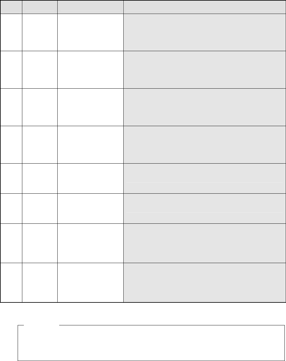
5. Detailed Explanation of the Recognition Errors of Area Array Components
(Whose Outer Side Is To Be Recognized)
‘RES M N Type Index 8 ErrCode …..’
M: Number of components recognized at the same time
N: Phase number for simultaneous component recognition
Type: component type
PBGA, CBGA, LGA
Index: Component identification number
Err
Code
.............. Description of an error Assumed cause
0 The system failed to
detect a ball(s) located
on the top side of the
component perimeter.
− This error occurs when the ball detection area on the top side is
not set correctly due to the stains stuck around the top side of
the VCS screen.
− This error occurs also when the number of balls detected on the
top side is one-thirds or less of the number you set because a
ball(s) is (are) stained.
1 The system failed to
detect a ball(s) located
on the bottom side of the
component perimeter.
− This error occurs when the ball detection area on the bottom side
is not set correctly due to the stains stuck around the bottom side
of the VCS screen.
− This error occurs also when the number of balls detected on the
bottom side is one-thirds or less of the number you set because
a ball(s) is (are) stained.
2 The system failed to
detect a ball(s) located
on the left side of the
component perimeter.
− This error occurs when the ball detection area on the left side is
not set correctly due to the stains stuck around the left side of the
VCS screen.
− This error occurs also when the number of balls detected on the
left side is one-thirds or less of the number you set because a
ball(s) is (are) stained.
3 The system failed to
detect a ball(s) located
on the right side of the
component perimeter.
− This error occurs when the ball detection area on the right side is
not set correctly due to the stains stuck around the right side of
the VCS screen.
− This error occurs also when the number of balls detected on the
right side is one-thirds or less of the number you set because a
ball(s) is (are) stained.
4 1 The row of balls located
on the top side of the
component perimeter is
not parallel with that on
the bottom side.
− An electrode or substance similar with a ball is located on balls of
the top and bottom sides of the component perimeter. When
such substances cannot be removed, this error occurs.
4 2 The row of balls located
on the left side of the
component perimeter is
not parallel with that on
the right side.
− An electrode or substance similar with a ball is located on balls of
the left and right sides of the component perimeter. When such
substances cannot be removed, this error occurs.
4 3 The distance between
the ball rows of the top
and bottom sides of the
component perimeter is
abnormal.
− The ball pitch is not set correctly.
− This error occurs when the system does not detect any ball on
either side, top or bottom, and detects the row of balls located
inside by one row as the ball row located on the component
perimeter.
− The system recognized a different BGA component.
4 4 The distance between
the ball rows of the left
and right sides of the
component perimeter is
abnormal.
− The ball pitch is not set correctly.
− This error occurs when the system does not detect any ball of
either side, left or right, and detects the row of balls located
inside by one row as the ball row located on the component
perimeter.
− The system recognized a different BGA component.
RES 1 1 PBGA 0 8 4 3
Description of an error: Abnormal is the distance between the ball rows located on the top
and bottom sides of the perimeter of a PBGA component whose ID is “0”.
Example
262
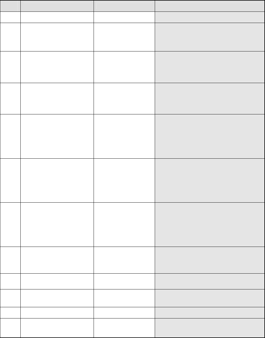
6. Detailed Explanation of the Recognition Errors of Area Array Components
(Whose All Balls Are To Be Recognized)
‘RES M N Type Index 8 ErrCode …..’
M: Number of components recognized at the same time
N: Phase number for simultaneous component recognition
Type: component type
PBGA_ALL, LGA_ALL
Index: Component identification number
Err
Code
Description of an error Assumed cause
7 Pitch The ball pitch is
abnormal.
− A wrong ball pitch is entered.
8 0 A ball(s) is (are) too dark. − This error occurs when a ball(s) cannot be
displayed clearly due to its (their) stains or
oxidation.
− The light amount is deteriorated.
− The light does not turn on.
8 4 3 The distance between
the ball rows of the top
and bottom sides of the
component perimeter is
abnormal.
− The ball pitch is not set correctly.
− This error occurs when the system can
detect no ball of either side, top or bottom,
and detects the row of balls located inside by
one row as the ball row located on the
component perimeter.
8 4 4 The distance between
the ball rows of the left
and right sides of the
component perimeter is
abnormal.
− The ball pitch is not set correctly.
− This error occurs when the system can
detect no ball of either side, left or right, and
detects the row of balls located inside by one
row as the ball row located on the
component perimeter.
8 5 The system failed to
generate the frame for
detecting all balls.
− The ball pitch or diameter is not set correctly.
− This error occurs when a component is
inclined much.
− This error occurs also when there is a
substance that reflects light easily such as a
mark around the perimeter of the package.
− The system has not performed calibration
(setting of the pixel rate).
8 6 Raw Col S ErLv Dir
(ABS)
The ball area error
occurs.
− This error occurs when a ball is chipped.
− This error occurs also when a ball(s) is (are)
not displayed clearly due to its (their) stains
or oxidation.
− This error occurs also when the actual ball
diameter is different from that you set.
− This error occurs also when a balls is
deformed entirely.
8 7 Raw Col D ErLv
(ABS)
The ball diameter error
occurs.
− This error occurs when a ball is chipped.
− This error occurs also when a ball(s) is (are)
not displayed clearly due to its (their) stains
or oxidation.
− This error occurs also when the actual ball
diameter is different from that you set.
− This error occurs also when a ball is
deformed entirely.
8 8 Raw Col L Lth The ball brightness is
abnormal.
− This error occurs also when a ball(s) is (are)
not displayed clearly due to its (their) stains
or oxidation.
− The system detects a ball that is displayed
far more darkly than any other ball.
8 9 En Raw Col Dia There is no ball
(diameter error)
− This error occurs when the ball diameter is
very abnormal because a ball is chipped or
due to a bridge.
8 10 En Raw Col V Vth There is no ball (ball
brightness error)
− The tip of a ball is chipped.
− This error occurs when a ball is chipped
much.
8 11 The number of sampled
balls is not enough.
− The system detects only two or less balls
correctly due to stains or oxidation of balls.
8 12 0 The system failed to
position a component.
− The ball assignment setting is not correct.
− A wrong ball diameter is entered.
− The hardware malfunctions.
263
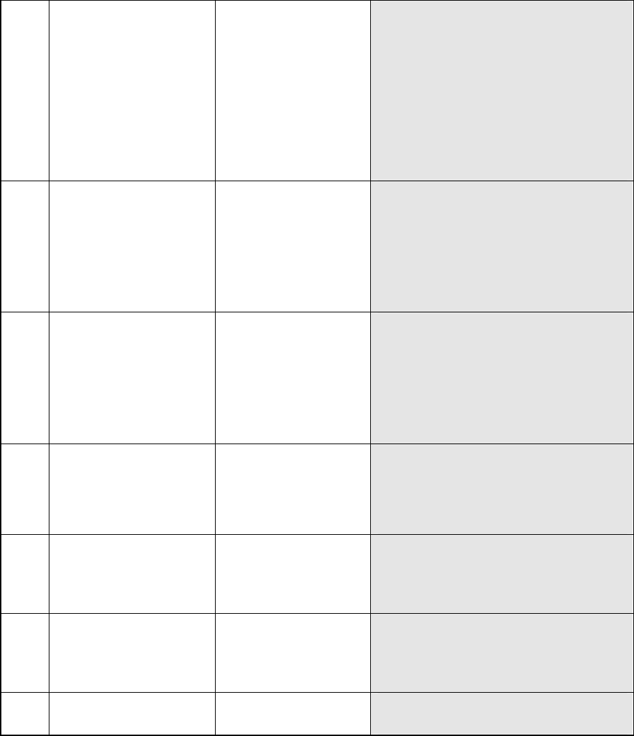
8 12 0 RC1 504 RC2 The system failed to detect
any ball.
− This error occurs due to a wrong component
type.
− This error occurs also when a component is
not picked up.
− This error occurs also when a ball(s) is (are)
not displayed clearly due to its (their) stains
or oxidation.
− This error occurs also when the light does
not turn on.
− This error occurs also when contrast
between a ball and its background is low.
− This error occurs also when there are many
balls and many substances similar with a ball
on a component.
8 12 0 RC 508 RC2 The system failed to
position a component.
− The ball assignment setting is not correct.
− A wrong ball diameter is entered.
− This error occurs also when a ball(s) is (are)
not displayed clearly due to its (their) stains
or oxidation.
− This error occurs also when contrast
between a ball and its background is low.
− This error occurs when there are many
marks or other substances similar with a ball
on a component.
8 12 0 RC1 510 RC2 Time-out error (It takes four
seconds or more for the
system to recognize a
component, then the
system interrupts
recognition of the
component. This error
occurs at the VCS whose
version is 1.11AF or later.)
− The ball assignment setting is not correct.
− A wrong ball diameter is entered.
− This error occurs also when a ball(s) is (are)
not displayed clearly due to its (their) stains
or oxidation.
− This error occurs also when contrast
between a ball and its background is low.
− This error occurs when there are many
marks or other substances similar with a ball
on a component.
8 12 5 Raw Col The system failed to find
any ball.
− The ball pitch or diameter is not entered
correctly.
− This error occurs also when there is a
substance that reflects light easily such as a
mark around the perimeter of the package.
− The system has not performed calibration
(setting of the pixel rate).
8 12 6 Raw Col S ErLv
(ABS)
The ball area error occurs. − This error occurs when a ball is chipped.
− This error occurs also when a ball(s) is (are)
displayed clearly due to its (their) stains or
oxidation.
This error occurs also when a ball is deformed
entirely.
8 12 7 Raw Col D ErLv
(ABS)
The ball diameter error
occurs.
− This error occurs when a ball is chipped.
− This error occurs also when a ball(s) is (are)
displayed clearly due to its (their) stains or
oxidation.
− This error occurs also when a ball is
deformed entirely.
8 16 Xd Yd The correction amount
between divided views is
abnormal.
− The distance between views is not set
correctly.
− The view angle is not set correctly.
Pitch: Detected ball pitch (mm)
Row: Row number of a ball at which the system detected an error
(0, 1, 2 … viewed from the top of the screen)
Col: Column number of a ball at which the system detected an error
(0, 1, 2 … viewed from the left side of the screen)
S: Area of a ball at which the system detected an error (mm2)
D: Diameter of a ball at which the system detected an error (mm)
ErLv: Error ratio of a ball at which the system detected an error (%)
(ABS): Difference between the average value of all ball dimensions and those already set
(%)
Rc1: Main error code internally processed with VCS
Rc2: Sub error code internally processed with VCS
“Rc1” and “Rc2” show the internal recognition block or internal evaluation parameter used with
VCS. These do not show the direct (physical) cause of an error, but are necessary for
analyzing the error. Let us know these numbers when you contact us.