KE2010.Instruction Manual.Ver.2.01,Rev.08.pdf - 第1079页
274 D. Detailed Explanati on of the Coplanari ty Er rors 1. Detailed Explanation of the Coplanarity Check Result Display ed on the VCS Monitor The res ult for m easuring a c omponent ter m inal with the coplanarity senso…
273
ELGNum: Element group number at which the system detected an error
Pos: Ball number at which the system detected an error (1 to )
Pitch: Ball pitch detected (mm)
S: Area of a ball at which the system detected an error (mm2)
D: Diameter of a ball at which the system detected an error (mm)
ErLv: Error ratio of a ball at which the system detected an error (%)
En: Number of balls at which the system detected an error with its ball existence check
Dia: Diameter of a ball at which the system detected an error first with its ball existence check
V: Luminance of a ball at which the system detected an error first with its ball existence check
Vth: Ball luminance judgment value used with the ball existence check
Rc1: main error code internally processed with VCS
Rc2: Sub error code internally processed with VCS
“Rc1” and “Rc2” indicate the VCS internal recognition block or internal evaluation parameter. These do
not show the direct (physical) cause of an error, but are necessary for analyzing the error. Let us know
these numbers when you contact us.
RES 1 1 RDM_BALL 0 8 12 5 1 10
Description of the error: The system failed to detect the 10
th
ball of the first element group
on a general-purpose vision ball component whose ID is “0”.
11. Detailed Explanation of an Aluminum Electrolytic Capacitor/GaAsFET
Recognition Error
‘RES M N Type Index ErrCode …’
M: Number of components recognized at the same time
N: Phase numbers recognized at the same time
Type: Component type
TER2 (Aluminum electrolytic capacitor), TER4 (GaAsFET)
Index: Component ID number
Err
Code
Description of an error Assumed cause
4 side No lead could be detected. − An error occurred when the system could
not set the lead detecting window since
the VCS was stained.
− Vision data (lead length) was set
improperly.
* A value ± 30 % of the lead length you
set is judged as a correct length.
7 side Abnormal lead width − Vision data (lead width) was set
improperly.
* A value ± 20 % of the lead width you
set is judged as a correct width.
12 Abnormal dimensions − Vision data (dimensions) was set
improperly.
* A value 50 % to 120 % of the
dimension you set is judged as a
correct dimension.
Side: Side on which the system detected an error
(0: Top side 1: Bottom side 2: Left side 3: Right side)
RES 1 1 TER2 0 12
Description of the error: The dimensions of the aluminum electrolytic capacitor whose ID
is “0” are abnormal.
Example
Example
274
D. Detailed Explanation of the Coplanarity Errors
1. Detailed Explanation of the Coplanarity Check Result Displayed on the
VCS Monitor
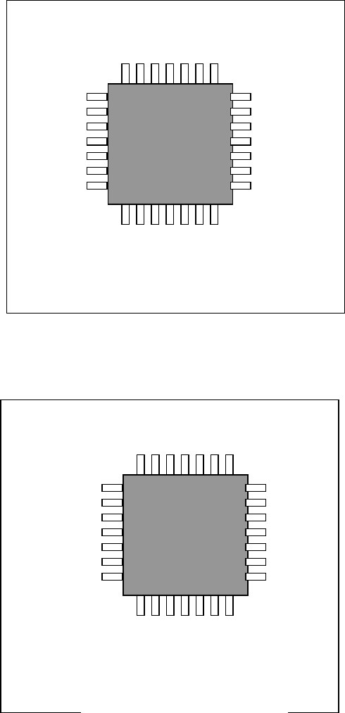
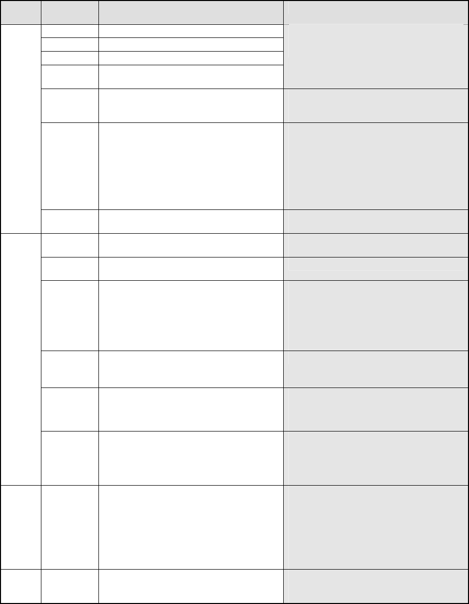
The result for measuring a component terminal with the coplanarity sensor is displayed on the
VCS monitor as well as the main unit monitor as shown below. The examples of the result
obtained if the system measured a component normally and that if it detected a measurement
error are shown in the figures below.
■ When the system measures a component normally
■ When an measurement error occurs
COPLA_OK
MJGFABS
COPLA_ERROR:1
3080
275
2. Detailed Explanation of the Coplanarity Errors
MJG Err
COPLA_ERROR: ErrCode
Err. Err
Code
Description of an error Cause
21-1000 Software operation environment error
15-1010 PC internal memory error
17-1060 Sensor head internal laser diode error
20-1070 Signal-processing board internal memory
error
If the system does not recovery from the
error at re-power on, the sensor may
malfunction.
18-1080 The sensor cable is not connected. Electric contact of the coplanarity sensor
cable*1 may be poor. Turn on the
system again.
19-1090 The scanner inside the sensor head does
not rotate normally.
− The sensor head is not supplied with
DC 24 V.
− The sensor scanner does not rotate.
If either of the problems above does
not occur, and the system does not
recover from the error even after
re-power on, the sensor may
malfunction.
FSYS
17-1100 Laser is turned off. Electric contact of the coplanarity sensor
cable*1 may be poor.
12-2010 The system received an illegal command
during adjustment of the sensor height.
Electric contact of the coplanarity 232C
cable*2 may be poor.
12-2030 The identifier of the command the system
sent is illegal.
− The mounter software malfunctions.
12-2040 After measurement, the system did not
recognize the measurement start signal
within 10 seconds.
− Electric contact of the coplanarity
interface cable*3 is poor.
− Any encoder pulse may not be output
from the XMP relay board.
− Any start trigger signal may not be
output from the carry relay board.
12-2050 An illegal command is issued.
A parameter that is out of the allowable
input range is set.
− The mounter software malfunctions.
12-2060 No component information is registered.
No measurement image is obtained.
− The mounter software malfunctions.
(Before finishing measurement of a
component, the software sent other
command to the sensor.)
FOPE
12-2070 The inappropriate measurement mode is
selected.
− The measurement mode you selected
is inappropriate. Check the
component and check to see if the
selected measurement mode is
appropriate for it.
FCO
P
1-3000 The measured coplanarity value exceeds
the allowable range.
− This is not a system error. Display
the obtained image with a VGA
switching device or check the check
box “Stop system on any error” on the
Production (Pause) tab invoked from
the Operation option dialog box to
display the detailed information and
check an error terminal.
FPOS 2-3010 The shifted terminal position exceeds the
allowable range.
− This error may occur when a
component slides from the regulated
position.