KE2010.Instruction Manual.Ver.2.01,Rev.08.pdf - 第1348页
265 7. Detailed Explanation of the Recognition Errors of A rea A rray Components (Whose A ll Ceramic Balls A re To Be Recognized) ‘RES M N CBGA_ALL Index E rrC ode …..’ M: Num ber of c om ponents recognized at the sam e …
264
Example
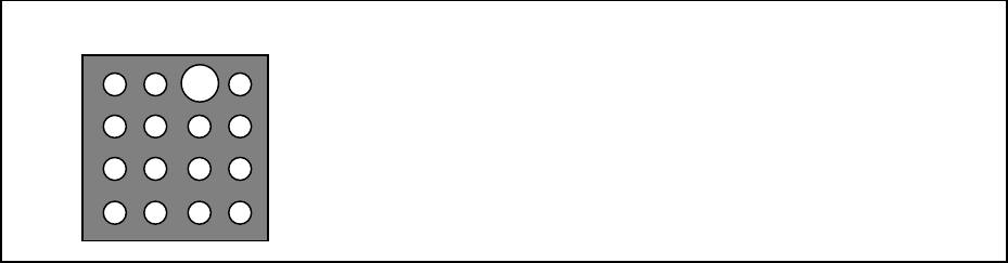
RES 1 1 PBGA_ALL 0 8 7 0 2 0.6 65.0
Description of the error: The diameter of a ball located at the
Row 0 and Column 2 of a BGA
component whose ID is “0” is abnormal
by 65 %.
(When the system detected the ball diameter as 0.99 mm
although the value already set is 0.6 mm.)
Dir: Direction of a ball at which the system detected an error
(0: upper or lower direction 1: left or right direction)
L: Brightness of a ball at which the system detected an error (0 to 255)
Lth: Judgment value of the ball brightness (0 to 255)
En: Ball number at which the system detected an error with its ball existence check
Dia: Diameter of a ball at which the system detected an error first with its ball existence check
(Pixel).
V: Luminance of a ball at which the system detected an error first with its ball existence
check.
Vth: Judgment value of the ball luminance used for ball existence check
Xd: Horizontal correction amount for an error
Yd: Vertical correction amount for an error
The values “V” and “Vth” are used to judge the average luminance value (0 to 255) in some
cases, or used to judge the total luminance value in other cases.
If either “V” or “Vth” exceeds 255, these values are used to judge the total luminance value.
1 2 3
0
1
2
3
265
7. Detailed Explanation of the Recognition Errors of Area Array Components
(Whose All Ceramic Balls Are To Be Recognized)
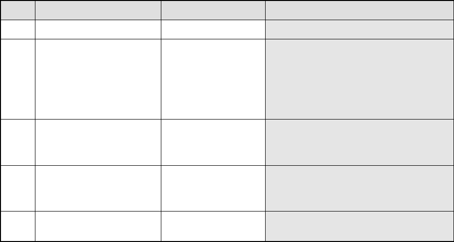
‘RES M N CBGA_ALL Index ErrCode …..’
M: Number of components recognized at the same time
N: Phase number for simultaneous component recognition
Index: Component identification number
Err
Code
Description of an error Assumed cause
8 The system failed to find
a component.
− This error occurs when the straight section of
the component perimeter is not clear.
8 5 Raw Col The system failed to find
a ball.
− This error occurs when there is no ball on a
component.
− This error occurs also when the shadow of
the ball bottom section cannot be displayed
clearly due to the ball shape, ball
assignment, and/or body color.
− This error occurs also when the center of a
component does not match with that of the
ball matrix.
8 6 Raw Col S ErLv The ball area error
occurs.
− This error occurs when a ball is chipped.
− This error occurs also when the shadow of
the ball bottom section cannot be displayed
clearly due to the ball shape, ball
assignment, and/or body color.
8 7 Raw Col D ErLv The ball diameter error
occurs.
− This error occurs when a ball is chipped.
− This error occurs also when the shadow of
the ball bottom section cannot be displayed
clearly due to the ball shape, ball
assignment, and/or body color.
8 16 Xd Yd Correction amount
between the divided
views is abnormal.
− The distance between views is not set
correctly.
− The view angle is not set correctly.
Row: Row number of a ball at which the system detected an error
(0, 1, 2 … viewed from the top of the screen)
Col: Column number of a ball at which the system detected an error
(0, 1, 2 … viewed from the left side of the screen)
S: Area of a ball at which the system detected an error (mm2)
D: Diameter of a ball at which the system detected an error (mm)
ErLv: Error ratio of a ball at which the system detected an error (%)
Xd: Horizontal correction amount for an error
Yd: Vertical correction amount for an error
266
8. Detailed Explanation of the Recognition Errors of Outline-Recognized
Components
‘RES M N Type Index 8 ErrCode …..’
M: Number of components recognized at the same time
N: Phase number for simultaneous component recognition
Type: component type
OFC, HIC, LTFM, BRCP
Index: Component identification number
Err Code Description of an error
0 The system failed to find a component.
1 The component size is abnormal.
2 There is no target pattern on a component.
3 The relative angle of a mark is abnormal.
4 The relative distance of a mark is abnormal.
5 Detail The internal algorithm detected an error.
Detail: Detailed information of the VCS internal error code.
“Detail” is a 5-digit internal recognition block or internal evaluation parameter of the VCS. The
lower 3 digits describe an error as shown in Table below. The fourth and fifth digits do not
specify the direct (physical) cause of an error, but are necessary for analyzing an error. Let us
know these numbers when you contact us.
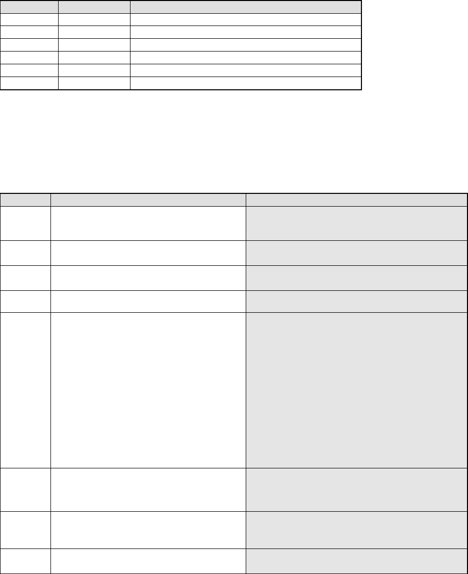
Number Description of an error Assumed cause
021 The center is out of the coordinate system.
− Whole of the component is not displayed inside the
screen.
− The component dimensions data is wrong.
031 No edge is detected at a side or corner.
− There is no component within the window.
− The binary threshold is not appropriate.
041 No straight line can be extracted at a side or
corner.
− A straight line shown on the window is too short.
− The edge does not indicate a straight line.
051 Two straight lines are parallel with one another at
the detected side or corner.
052 The angle between two straight lines at the
detected side or corner exceeds the allowable
value.
The angle at which two straight lines are crossed is not
90 degrees.
The allowable angles are shown below.
When a corner is detected: ±0.24 rad
When a side is detected: ± 0.03 rad
When positions of four corners are checked:
± 0.05 rad
− The angle of a component corner is not 90 degrees.
− The system recognizes a straight line incorrectly.
(Because two parallel straight lines are located
closely on the window, or other reasons.)
− The angle generated with three of four corners
detected is not 90 degrees.
053 A point of intersection of two straight lines at the
detected side or corner is out of the coordinate
system.
− A component whose corner is very round is inclined
and displayed at the corner of the screen.
− The corner of a component is not displayed on the
screen.
054 The inclination of a straight line exceeds the
allowable range.
− The edge detected is uneven.
− A component is inclined 10 degrees or more
− The detected side is inclined 10 degrees or more.
062 The system cannot calculate the inclination of a
component after detecting its gravity.
− A component is inclined 30 degrees or more.
− A component has no direction.