KE2010.Instruction Manual.Ver.2.01,Rev.08.pdf - 第1350页
267 091 The c omponent length error oc curs. − The s ystem pic ked up the wrong com ponent. − The s etti ng of the all owable range is inappropriate. − The syst em rec ognized the detec ted st raight li ne incor rectly .…
266
8. Detailed Explanation of the Recognition Errors of Outline-Recognized
Components
‘RES M N Type Index 8 ErrCode …..’
M: Number of components recognized at the same time
N: Phase number for simultaneous component recognition
Type: component type
OFC, HIC, LTFM, BRCP
Index: Component identification number
Err Code Description of an error
0 The system failed to find a component.
1 The component size is abnormal.
2 There is no target pattern on a component.
3 The relative angle of a mark is abnormal.
4 The relative distance of a mark is abnormal.
5 Detail The internal algorithm detected an error.
Detail: Detailed information of the VCS internal error code.
“Detail” is a 5-digit internal recognition block or internal evaluation parameter of the VCS. The
lower 3 digits describe an error as shown in Table below. The fourth and fifth digits do not
specify the direct (physical) cause of an error, but are necessary for analyzing an error. Let us
know these numbers when you contact us.
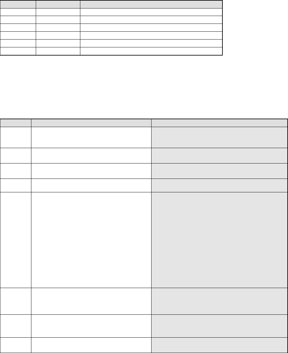
Number Description of an error Assumed cause
021 The center is out of the coordinate system.
− Whole of the component is not displayed inside the
screen.
− The component dimensions data is wrong.
031 No edge is detected at a side or corner.
− There is no component within the window.
− The binary threshold is not appropriate.
041 No straight line can be extracted at a side or
corner.
− A straight line shown on the window is too short.
− The edge does not indicate a straight line.
051 Two straight lines are parallel with one another at
the detected side or corner.
052 The angle between two straight lines at the
detected side or corner exceeds the allowable
value.
The angle at which two straight lines are crossed is not
90 degrees.
The allowable angles are shown below.
When a corner is detected: ±0.24 rad
When a side is detected: ± 0.03 rad
When positions of four corners are checked:
± 0.05 rad
− The angle of a component corner is not 90 degrees.
− The system recognizes a straight line incorrectly.
(Because two parallel straight lines are located
closely on the window, or other reasons.)
− The angle generated with three of four corners
detected is not 90 degrees.
053 A point of intersection of two straight lines at the
detected side or corner is out of the coordinate
system.
− A component whose corner is very round is inclined
and displayed at the corner of the screen.
− The corner of a component is not displayed on the
screen.
054 The inclination of a straight line exceeds the
allowable range.
− The edge detected is uneven.
− A component is inclined 10 degrees or more
− The detected side is inclined 10 degrees or more.
062 The system cannot calculate the inclination of a
component after detecting its gravity.
− A component is inclined 30 degrees or more.
− A component has no direction.
267
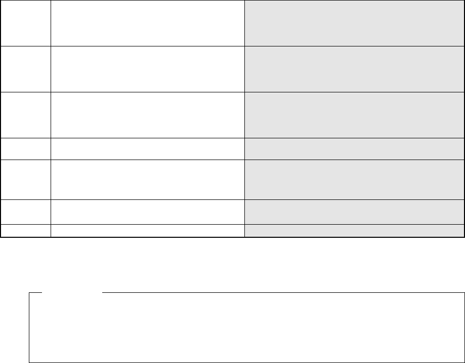
091 The component length error occurs.
− The system picked up the wrong component.
− The setting of the allowable range is inappropriate.
− The system recognized the detected straight line
incorrectly.
092 The component width error occurs.
− The system picked up the wrong component.
− The setting of the allowable range is inappropriate.
− The system recognized the detected straight line
incorrectly.
093 The component length/width error occurs.
− The system picked up the wrong component.
− The setting of the allowable range is inappropriate.
− The system recognized the detected straight line
incorrectly.
010 The component size error occurs.
− The component aspect ratio is less than 1.2 (the
longer side to the shorter side).
102 The gravity detection error occurs.
− The system picked up the wrong component.
(The specified component dimensions indicate that
the shape of a component is a rectangle, but the
detected shape is a square.)
103 The system did not detect the inclination of a
component correctly when recognizing its gravity.
− The system picked up the wrong component.
− The specified component placement angle is wrong.
999 Other errors
− The hardware malfunctions.
RES 1 1 0FC 0 5 **052
Description of the error: When the system detects a side and corner of an
outline-recognized component whose ID is “0”, it found that the angle of two straight lines
exceeds the allowable range.
Example
268
9. Detailed Explanation of the Recognition Errors of General-Purpose Vision
Components (Lead Components/Outline-Recognized Components)
‘RES M N MLT_LEAD Index ErrCode …..’
M: Number of components recognized at the same time
N: Phase number for simultaneous component recognition
Index: Component identification number
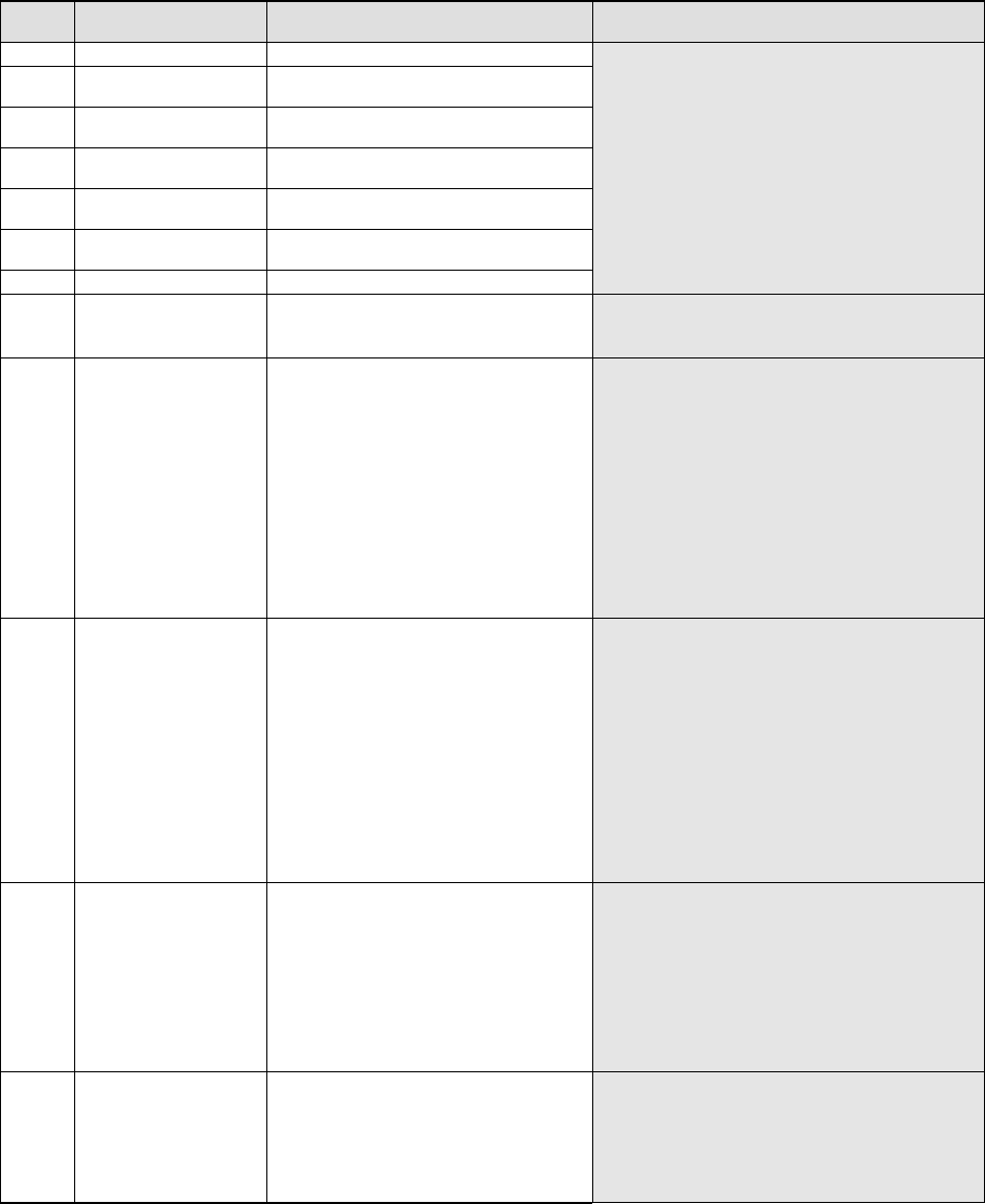
Err
Code
Description of an error Assumed cause
1 ELGNum Pos Bend A lead is bent.
2 ELGNum Num There are too few leads on a
component.
3 ELGNum Pos There is a lead whose length is
abnormal.
4 ELGNum The system did not detect any lead on a
component.
5 ELGNum Num There are only a few leads on a
component.
6 ELGNum Num There are too many leads on a
component.
7 ELGNum The lead pitch is abnormal.
− The causes of the errors described other
than “ELGNum” are the same as those for a
standard lead component.
8 12 0 The system failed to position a
component.
− The setting of the lead assignment is wrong.
− The entered lead width/length is wrong.
− The hardware malfunctions.
8 12 0 RC1 504
RC2
The system failed to detect any lead.
− This error occurs due to a wrong component
type.
− This error occurs also when a component is
not picked up.
− This error occurs also when a lead(s) is
(are) not displayed clearly due to its (their)
stains or oxidation.
− This error occurs also when the light does
not turn on.
− This error occurs also when contrast
between a lead and its background is low.
− This error occurs also when there are many
leads and many marks or substances
similar with a lead on a component.
8 12 0 RC21 508
RC2
The system failed to position a
component.
− The lead assignment setting is not correct.
− A wrong lead width/length is entered.
− This error occurs also when a lead(s) is
(are) not displayed clearly due to its (their)
stains or oxidation.
− This error occurs also when contrast
between a lead and its background is low.
− This error occurs when there are many
leads and marks or other substances
similar with a lead on a component.
− The actual lead length is shorter than the
specified length.
− This error occurs when the lead corner is
too round.
8 12 0 RC21 510
RC2
Time-out error (It takes four seconds or
more for the system to recognize a
component, and the system interrupts
recognition of the component. This
error occurs at the VCS whose version is
1.11AF or later.)
− The lead assignment setting is not correct.
− A wrong lead width/length is entered.
− This error occurs also when a lead(s) is
(are) not displayed clearly due to its (their)
stains or oxidation.
− This error occurs also when 8contrast
between a lead and its background is low.
− This error occurs when there are many
leads and marks or substances similar with
a lead on a component.
8 12 5 ELGNum
Pos
The system failed to detect a certain
lead of a lead group.
− The entered lead pitch, lead width or lead
length is wrong.
− This error occurs when there is a substance
similar with a mark around a lead.
− This error occurs also when the system has
not performed calibration (setting of the
pixel rate).